Airbag Wiring Diagram Air Ride

Airbag Suspension Valve Wiring Diagram Air Ride Solenoid

Airbag Suspension Wiring Diagram Gooddy Org In Airbags
Custom Aftermarket Air Ride Suspension Kit Installation

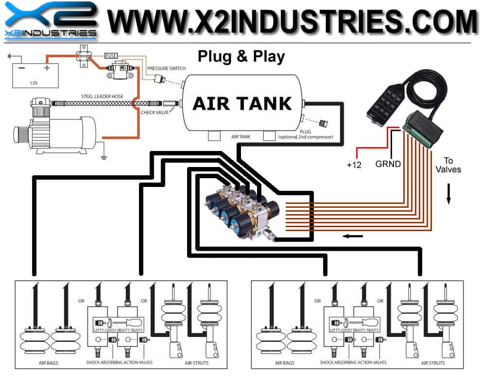
Connect the black wires pin 1 pin 3 to ground.
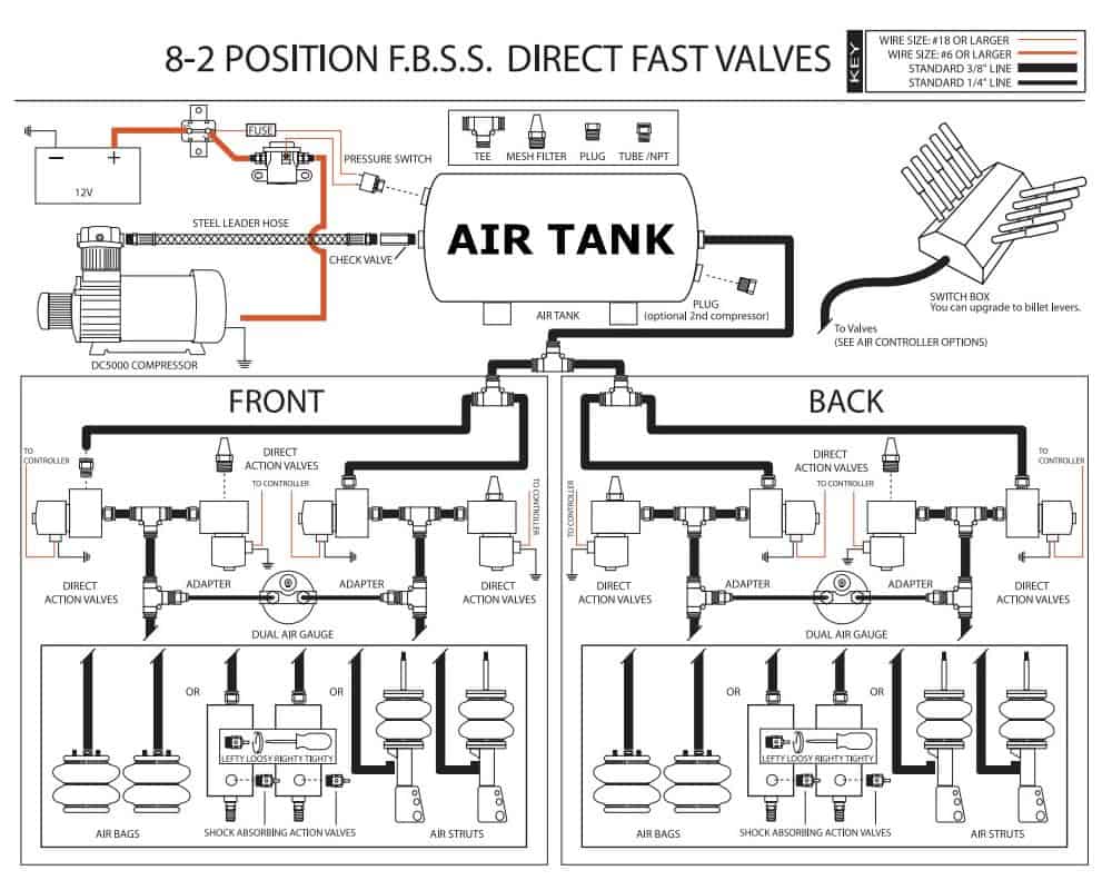
Airbag wiring diagram air ride. Connect the lcd controller to the relay control box. Whats up guys in this episode i will be starting the install for the airlift 3p kit. It reveals the components of the circuit as streamlined shapes as well as the power and also signal links between the gadgets. Mount the smart ride in a dry location away from hot exhaust and any moving components.
Upload pictures and videos create with the online photo editor or browse a photo gallery or album and create custom print products air ride valve wiring. Mount the smart ride in a dry location away from hot exhaust and any moving components. Smart ride complete digital air management system non plug n play installationnon plug n play installation 1. With 14 gauge primary wire from second terminal on pressure swirch to small switched terminal on top of the solenoid or terminal 85 on relay.
I hope you enjoy and make sure to. A wiring diagram is a streamlined standard photographic representation of an electrical circuit. If you need further help you can find more info below. Disconnect the negative battery terminal.
Here you will find installation plumbing and wiring instructions for all of our ez airride kits. Connect the lcd controller to the relay control box. Kelderman air ride wiring diagram welcome thank you for visiting this simple website we are trying to improve this website the website is in the development stage support from you in any form really helps us we really appreciate that. Fuse panel layout diagram parts.
How to complete air ride plumbing wiring s 10 forum best of airbag suspension diagram webtor. Determine where the lcd controller will be mounted. We will share this website for you articles and images of wiring diagrams engine schemes engine problems engine diagrams transmission diagrams. Plumbing two compressors get free image hosting easy photo sharing and photo editing.
Ignition switch cooling fan pcm power relay fuse injection fuel starting system fuse junction paenl driver power seat anti lock rear defrost accessory delay relay power window relay fuse junction panel air suspension charging system heated seat air suspension horn heated oxygen sensor vacuum regulator auxiliary power outlet. Installing an onboard air compressor to a pickup truck duration. Using switch wiring diagram run wires from assigned valves to switches with each valve solenoad being grounded at valve location. Assortment of air bag suspension wiring diagram.

Air Bag Schematics Wiring Schematic Diagram

Tractor Air Bag Schematic Wiring Diagram

Air Ride Schematic Wiring Schematic Diagram

Compressor Installation Instructions Airbagit Com

Basic Air Bag Set Up Diagram Rat Rod Air Ride Rat Rod

Air Bag Suspension Schematic Swift Electrical Schemes
Custom Aftermarket Air Ride Suspension Kit Installation

Air Bag Suspension Schematic Swift Electrical Schemes

Vw Airbag Wiring Diagram Wiring Schematic Diagram

Fuse Box Layout Wiring Diagram 9 3 Location Basic O Diagrams

Airbag Wiring Diagram Air Ride Wiring Diagram
Airbag Diagram The 1947 Present Chevrolet Gmc Truck

Air Bag Suspension Schematic Swift Electrical Schemes
Air Ride Causing Battery Drain The 1947 Present

Wiring Diagram For Firestone Level Command Ii On Board

Tractor Air Bag Schematic Wiring Diagram
Repair Guides

Wrg 9423 Air Ride Wiring Diagram
