Block Diagram Of A High Level Modulation

Am Transmitters
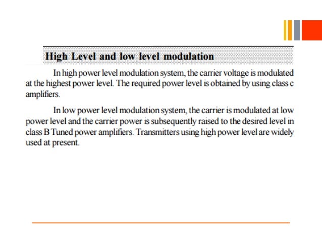
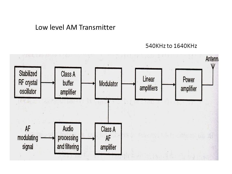
Engineering Made Easy Low Level And High Level Modulation

Communication Protocols Assignments Block Diagram Of Am
It is basically composed of a transmitter a transmission path and a receiver.
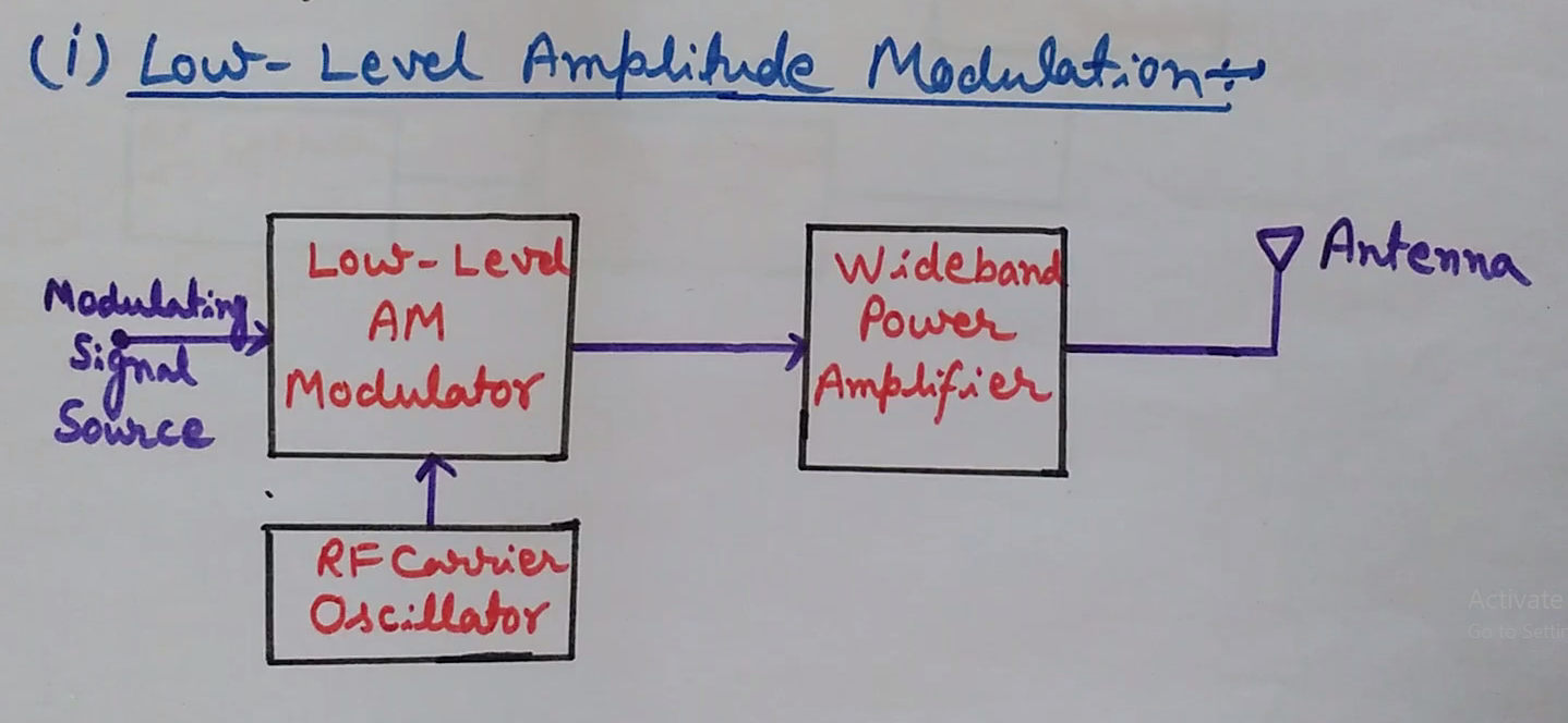
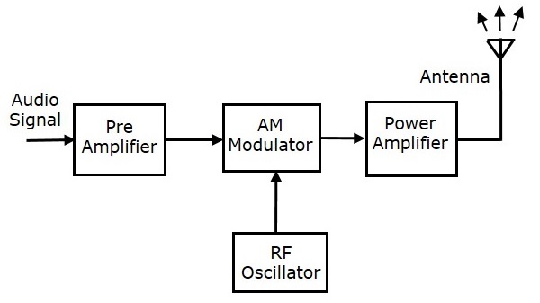
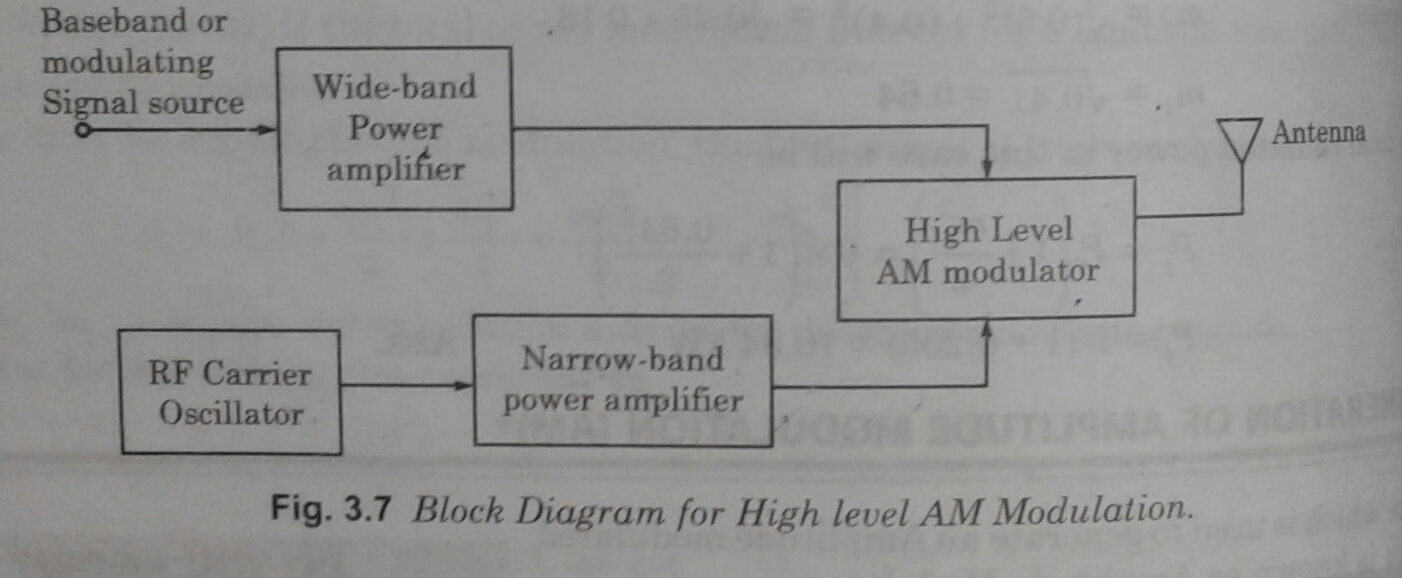
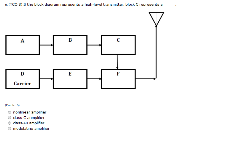
Block diagram of a high level modulation. In the high level transmitter the carrier signal and modulating signal is amplified using linear amplifiers. At the modulation block both signals are amplified with modulation and then fed to the antenna for transmission. This lecture covers low level and high level am modulation. The transmitter performs the sampling quantizing and encoding of the signal.
Low level and high level modulation block diagram of am transmitters high level low level for theory notes visit our blog httpstechoometryblogspotin if you like my video then subscribe to. The rf section begins just like the low level transmitter. Figure a is drawn for audio transmission. Block diagram of pulse code modulation.
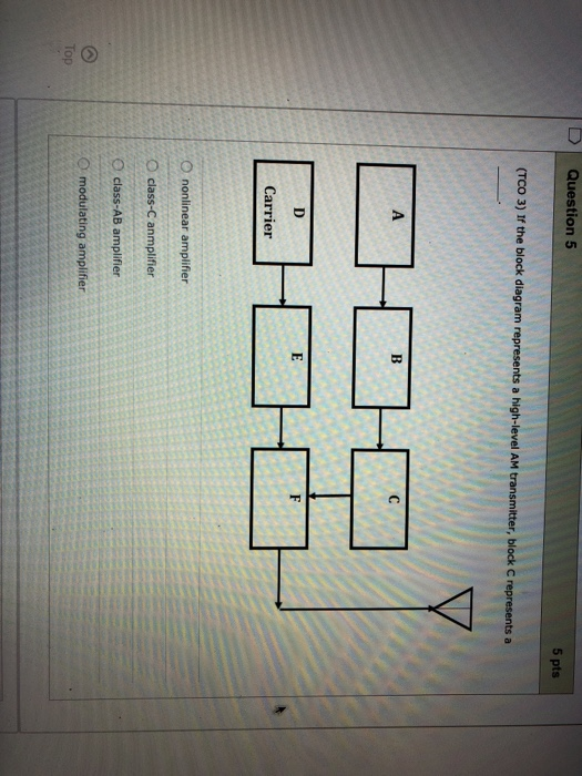
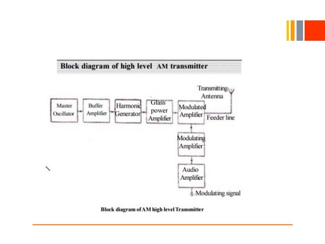
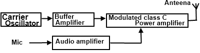
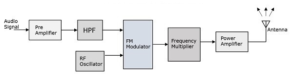
Figure a shows the block diagram of high level am transmitter. With low level modulation the modulation takes place prior to the output element of the final stage of transmitter. Signal that is to be transmitted is fed to a low pass filter that passes the low frequency component and eliminates the high frequency component. Low level and high level modulation block diagram am transmitter block diagram this post is about the generation of amplitude modulation.
Block diagram for delta modulation. As only 1 bit is used to encode 1 voltage level thus the technique allows transmission of only 1 bit per sample. Amplitude modulation am transmission and reception 23 23 am modulating circuits am modulators there are two levels of modulation. Below figures show the block diagram of high level and low level transmitters.
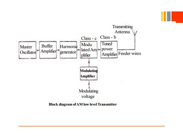
Figure a shows the block diagram of high level am transmitter. There is an oscillator and buffer amplifier. You will learn here what is amplitude modulation am and the generation of amplitude modulation am with the help of block diagram. Low level modulation and high level modulation.
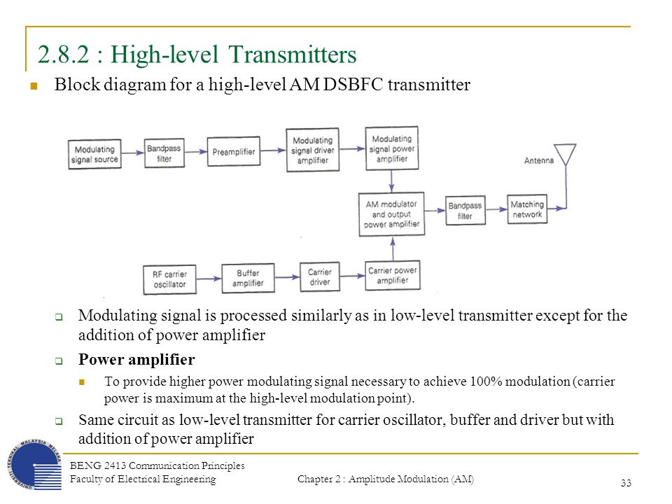
In high level transmission the powers of the carrier and modulating signals are amplified before applying them to the modulator stage as shown in figure a. The basic difference between the two transmitters is the power amplification of the carrier and modulating signals. The figure below shows the block diagram representing a pcm system. Here we will see two different ways of generating amplitude modulation am.
Block diagram of high level am transmitter. The difference in the high level transmitter is where the modulation takes place.
Am Transmitter
Analog Communication Transmitters Tutorialspoint

Am Transmitters

Write A Note On Low Level And High Level Modulation
Am Transmitter
Am Transmitter
Technical Blogger Generation Of Amplitude Modulation Am

Block Diagram Of A High Level Modulation Wiring Diagram

Am Transmitters
Chapter 2 Amplitude Modulation Am Transmission And
Solved If The Block Diagram Represents A High Level Trans

Low Level And High Level Modulation Generation Of Am Modulation Block Diagram Of Am Transmitter
Am Transmitters

Communication Systems Electronics And Communication
Am Transmitter
Analog Communication Transmitters Tutorialspoint

The Silicon Graybeard Radio Sunday 4 Modulation Basics
F1 X F2 Sum And Mixing Of Frequencies F Usb Fc Fm And F
