Block Diagram Of Signal Flow
Procedure To Convert Signal Flow Graph To Block Diagram With Example Control System
Solved Find The Signal Flow Graph For The Above Block Dia
Signal Flow Graph

Signal flow graphs are another method for visually representing a system.
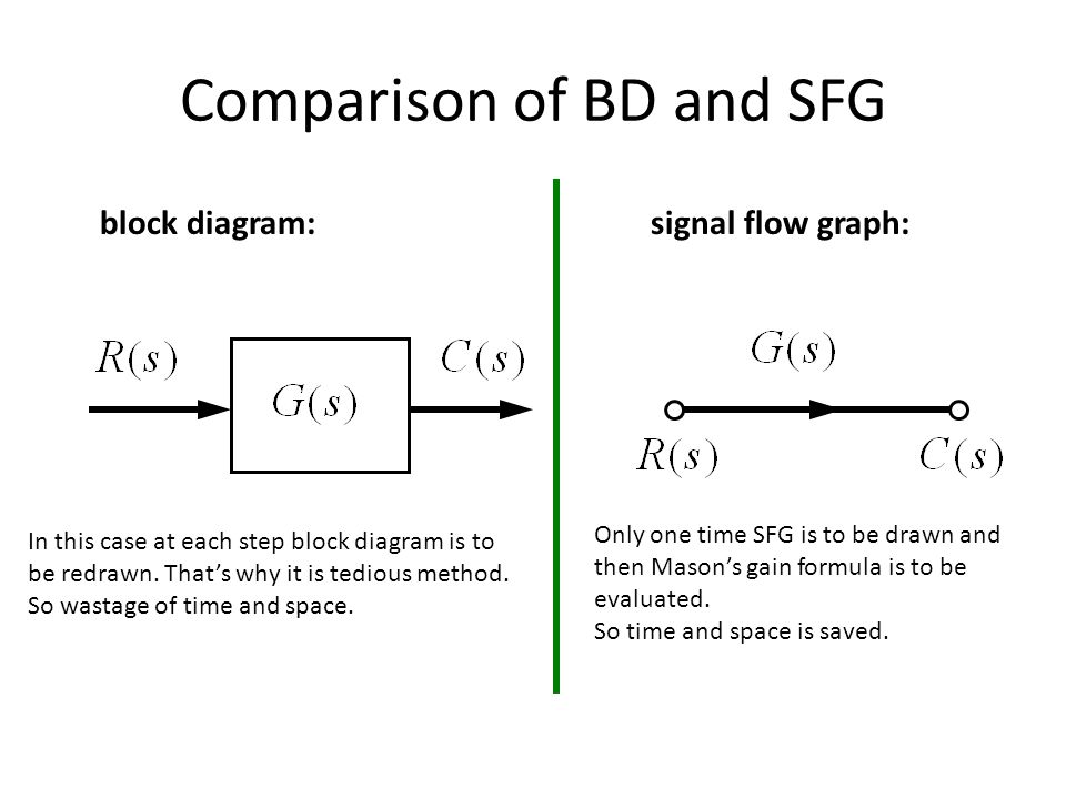
Block diagram of signal flow. Block diagrams consist of blocksthese represent subsystems typically modeled by and labeled with a transfer function signals inputs and outputs of blocks signal direction indicated by. Signal flow diagrams typically use curved lines to represent wires and systems instead of using lines at right angles and boxes respectivelyevery curved line is considered to have a. Rotational mechanical systems block diagrams signal flow graph method signal flow graph s. Conversion of block diagrams into signal flow graphs.
Signal flow diagrams are especially useful because they allow for particular methods of analysis such as masons gain formula. 1 1 2 4 1 x dt d x x 3 x dt x 1 3dt x 4 dt d dt d. Here the blocks of transfer function summing symbols and take off points are eliminated by branches and nodes. Signal flow graph of control system is further simplification of block diagram of control system.
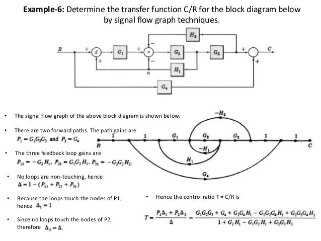
Webb mae 4421 3 block diagrams in the introductory section we saw examples of block diagrams to represent systems eg. Control systems block diagrams and signal flow graphs. Examples of block diagram signal flow example no. The transfer function is referred as transmittance in signal flow graph.
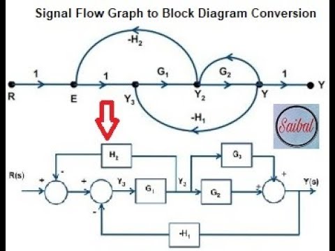
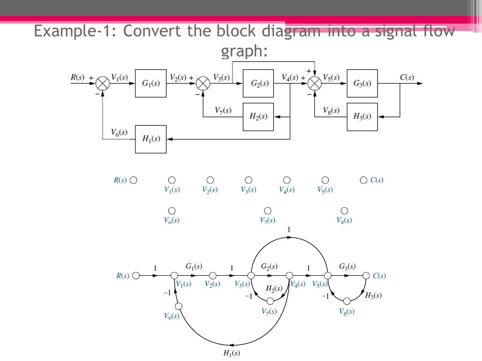
Follow these steps for converting a block diagram into its equivalent signal flow graph. It can be used together with transfer functions to describe the cause effect relationships throughout the systemthe common elements in block diagrams of most control systems include. Mason 1953 though the block diagram approach is commonly used for simple systems it quickly gets complicated when there are multiple loops and subsystems or in mimo cases. While x is the control signal.
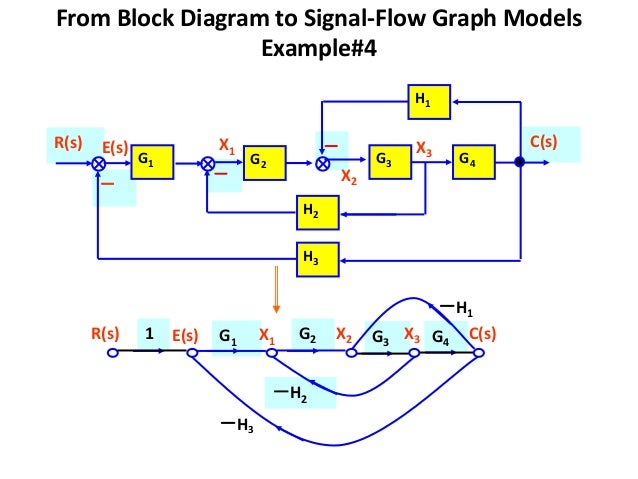
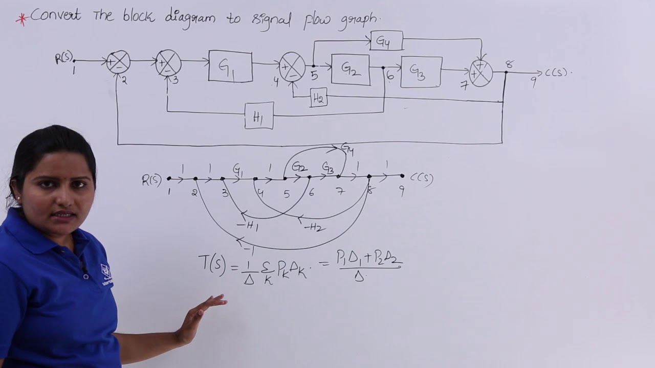
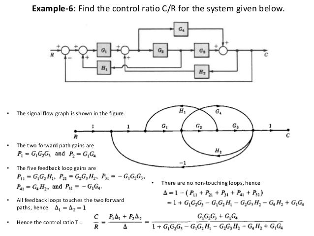
Let us take an example of. For other authors linear block diagrams and linear signal flow graphs are equivalent ways of depicting a system and either can be used to solve the gain. Represent all the signals variables summing points and take off points of block diagram as nodes in signal flow graph. 2 where the integrator differentiator and square root extractor are the control elements.
Draw a block diagram for the following equation. Step 6 signal flow graph of overall system is shown in the following figure.
Signal Flow Graph
Block Diagram And Signal Flow Graph Wiring Diagram
Problem 2 On Converting Block Diagram To Signal Flow Graph

A Block Diagram Of Efm1 And B Its Signal Flow Graph
File Block Diagram Signal Flow Graph Svg Wikimedia Commons
Control Systems Signal Flow Graphs Tutorialspoint
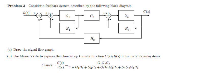
Solved Consider A Feedback System Described By The Follow

File Block Diagram Signal Flow Graph Svg Wikimedia Commons
Signal Flow Graph

Block Diagram To Signal Flow Chart Awesome Signal Flow Graph
Solved Verify Answer By Converting Block Diagram To Signa

Symbolic Reduction Of Block Diagrams And Signal Flow Graphs

Biomedical Control Systems Bcs Ppt Video Online Download

A Block Diagram Of The Components Of The System And The
Lecture On Signal Flow Graph Ppt Video Online Download

Ec Gate Block Diagram And Signal Flow Graph Online Test
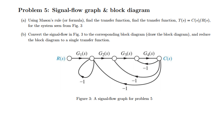
Solved Problem 5 Signal Flow Graph Block Diagram A U
Block Diagrams And Signal Flow Graphs
