Dc Motor Armature Winding Diagram
Dc Motor Armature Winding Question Physics Forums

How To Check A Motor Armature For Damaged Windings Groschopp
How To Check A Motor Armature For Damaged Windings Groschopp

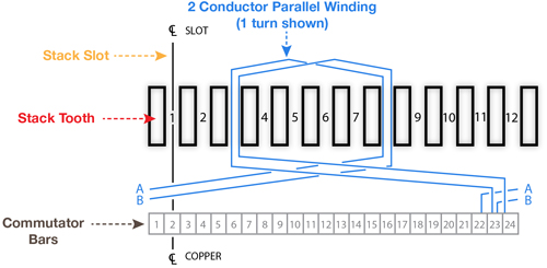
2 pole 12 slot 12 segment coil span.
Dc motor armature winding diagram. The location of the winding depends upon the type of machine. Generally there are two types of armature winding in the dc. Of the windingthis windings are same in both dc motor and dc generator. The armature windings conduct ac current even on dc machines due to the commutator action which periodically reverses current direction or due to electronical commutation as in brushless dc motorsthe armature can be on either the rotor rotating part or the stator stationary.
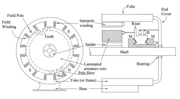
Its main function as far as the dc motor is concerned is to commute or relay the supply current from the mains to the armature winding housed over a rotating structure through the brushes of dc motor. A dc shunt motor also known as a shunt wound dc motor is a type of self excited dc motor where the field windings are shunted to or are connected in parallel to the armature winding of the motor. In this video you will learn about armature windings lap and wave type of armature windings equalizer rings and dummy coils. When voltage is applied current flows from power supply terminals through the series winding and armature winding.
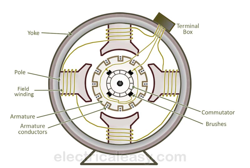
In other words we can say types of dc motors are purely based on how the field coil and armature is connected with each other. The current in the armature winding is known as the armature current. Armature winding must be connected in series with each other by means of end connections back connection and front connection in a manner so that the generated voltages of the respective coils will aid each other in the production of the terminal emf. The commutator of dc motor is a cylindrical structure made up of copper segments stacked together but insulated from each other by mica.
Dc series motor circuit diagram in a series motor electric power is supplied between one end of the series field windings and one end of the armature. Since they are connected in parallel the armature and field windings are exposed to the same supply voltage. Now the main classification of dc motor can be done by the different connections of field winding and armature winding. The difference between these two is merely due to the end connections and commutator connections of the conductor.
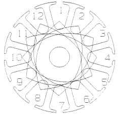
1 to 6 yc1 2 spool universal motor armature drawing with autocad. You can get an idea from the name itself. Basically armature winding of a dc machine is wound by one of the two methods lap winding or wave winding. The armature winding is the main current carrying winding in which the electromotive force or counter emf of rotation is induced.

Global Circuit Representation Of A 4 Wound Field Poles And 4

Armature Winding Lap Winding Connection Of Dc Machinne L 3 2
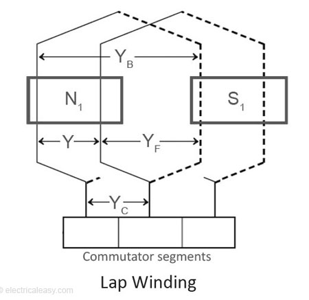
Armature Winding Of A Dc Machine Electricaleasy Com

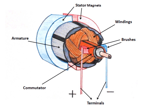
Construction Of Dc Motor Parts Images Electrical4u

Working Principal Of Dc Motor Construction Of Dc Motor

3d Winding Diagram Ald1v 1 1 1

Construction Of Dc Motor Your Electrical Guide

Physical Structure And Configuration Of Dc Machines

Working Principle Of Dc Motor Munir Academy

Juicer Armature Rewinding With Diagram Part 2 Of 2
Dc Motor Windings Electric Motors
Construction Of Dc Motor Electrical Concepts
Basic Construction And Working Of A Dc Generator
Dc Motor Basic Parts Electrical Machines Instrumentation

Construction Of Dc Motor Parts Images Electrical4u

Dc Motor Field Winding Designs
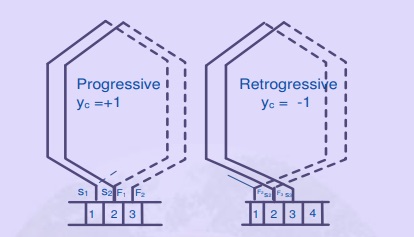
Types Of Armature Winding Lap Winding And Wave Winding

2 Induced Voltage In The Armature Winding Of Dc Motor
