Dc Motor Winding Diagram
Construction Of Dc Motor Electrical Concepts

Construction Of Dc Motor Your Electrical Guide

A Short Illustrated Primer On Brushed Dc Motors Precision

Always use wiring diagram supplied on motor nameplate.
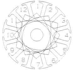
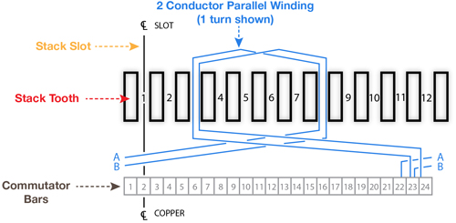
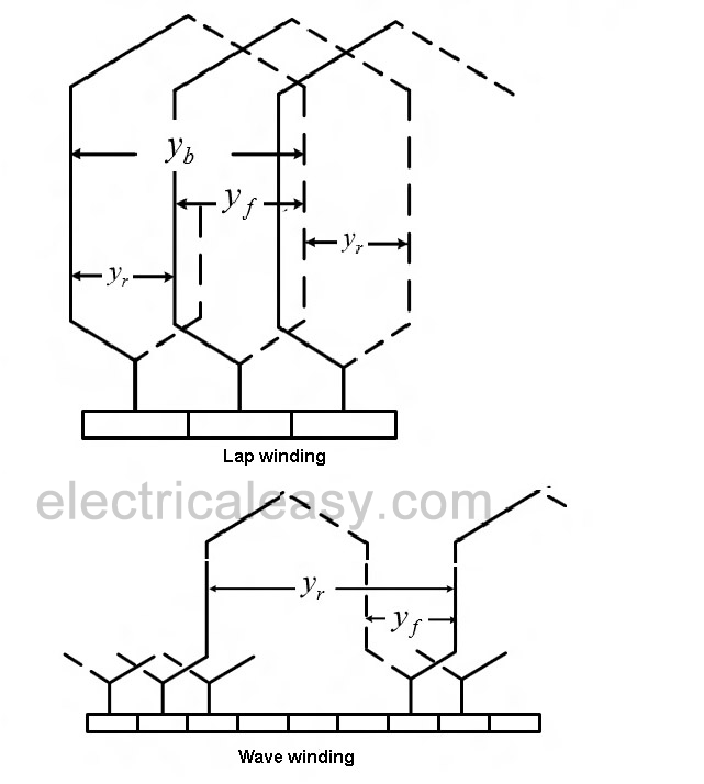
Dc motor winding diagram. Terminal markings and internal wiring diagrams single phase and polyphase motors meeting nema standards b. The difference between these two is merely due to the end connections and commutator connections of the conductor. Basically armature winding of a dc machine is wound by one of the two methods lap winding or wave winding. Use figure 1 if your motor has a single voltage shunt field.
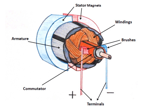
A brushed dc motor is an electromechanical motor driven by a dc power source. Motor wiring diagram dc. The diagram below shows this layout in an exploded view of a typical dc motor in this case a small o12mm. Three phase wiring diagrams always use wiring diagram supplied on motor nameplate.
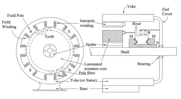
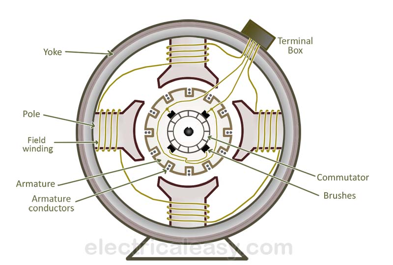
Brushed motors were the first commercially important application of electric power to driving mechanical energy and dc distribution systems were used for more than 100 years to operate motors in commercial and industrial buildings. Construction of dc motor. Brushes and terminals or leads. The basic parts of a brushed dc motor are.
Construction of dc motor nearly looks like the construction of dc generator originally when the dc machine starts working we cant identify whether its a dc generator or motor briefly dc motor consists of. Motor connections your motor will be internally connected according to one of the diagrams shown below. The commutator of dc motor is a cylindrical structure made up of copper segments stacked together but insulated from each other by mica. Which is the rotating part.
Armature winding must be connected in series with each other by means of end connections back connection and front connection in a manner so that the generated voltages of the respective coils will aid each other in the production of the terminal emf. Use figure 2 if your motor has a dual voltage shunt field. Of the windingthis windings are same in both dc motor and dc generator. Its main function as far as the dc motor is concerned is to commute or relay the supply current from the mains to the armature winding housed over a rotating structure through the brushes of dc motor.
When voltage is applied current flows from power supply terminals through the series winding and armature winding. Or leads are connected to the motor windings through the motor brushes. Dc series motor circuit diagram in a series motor electric power is supplied between one end of the series field windings and one end of the armature. These connections are in accordance with nema mg 1 and american standards publication 06.
A brushed dc electric motor is an internally commutated electric motor designed to be run from a direct current power source. If a single phase motor is single voltage or if either winding is intended for only one voltage the terminal marking shall be determined as follows.
Basic Construction And Working Of A Dc Generator
Dc Motor Windings Electric Motors

Dc Motor Field Winding Designs
Dc Motor Armature Winding Question Physics Forums

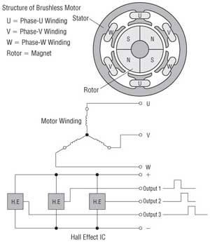
Brushless Dc Motor Winding Diagram Sensor Em 2019
How To Check A Motor Armature For Damaged Windings Groschopp
12 Pole Motor Wiring Diagram Wiring Diagram

Brushless Dc Motor Construction Working Principle And
Dc Motor Basic Parts Electrical Machines Instrumentation
Dc Motors And Stepper Motors Used As Actuators

日本電産株式会社
Speed Control Motor Systems Overview

Global Circuit Representation Of A 4 Wound Field Poles And 4

Physical Structure And Configuration Of Dc Machines

Dc Motors Padakuu Com
Armature Winding Of A Dc Machine Electricaleasy Com

Motor Stator Winding Diagram Wiring Schematic Diagram

Working Principal Of Dc Motor Construction Of Dc Motor
