In Out Wiring Diagram Fan

Ceiling Fan Wiring Diagram 1 For The Home Ceiling Fan

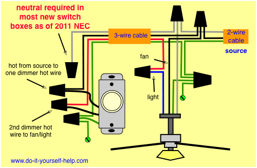
Wiring Diagrams For Lights With Fans And One Switch Read
Wiring Diagrams For A Ceiling Fan And Light Kit Do It

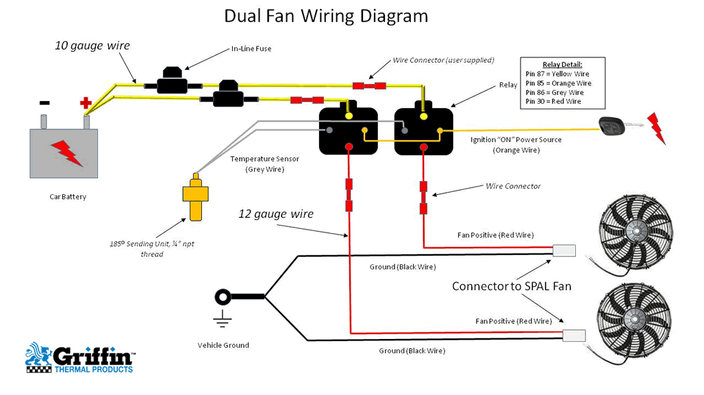
Cooling fan switch closes the circuit to engage the cooling fan when the optimum temperature is reached.
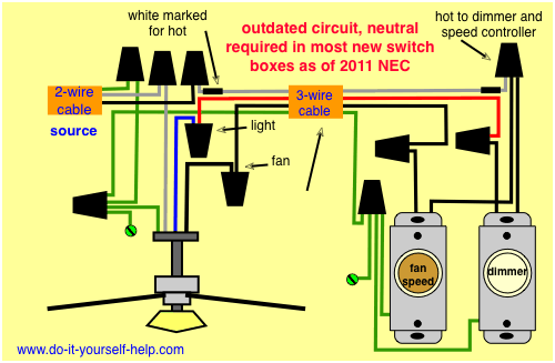
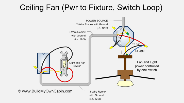
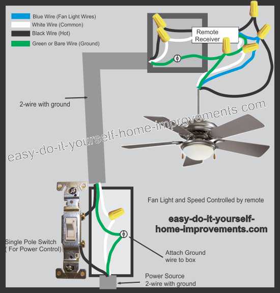
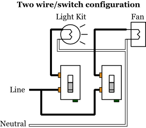
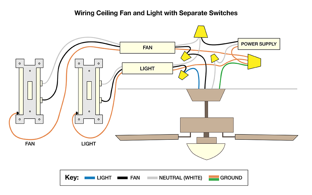
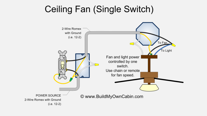
In out wiring diagram fan. This test will help you find out which speed a wire is on any psc blower motor. In this wiring the source is at sw1 and 3 wire cable runs between each switch and the ceiling fan. Attach the bare copper wire from your electrical box to the short green wire by twisting and orange wire connector to the two wires. Connect the black and blue wires coming out of your fan.
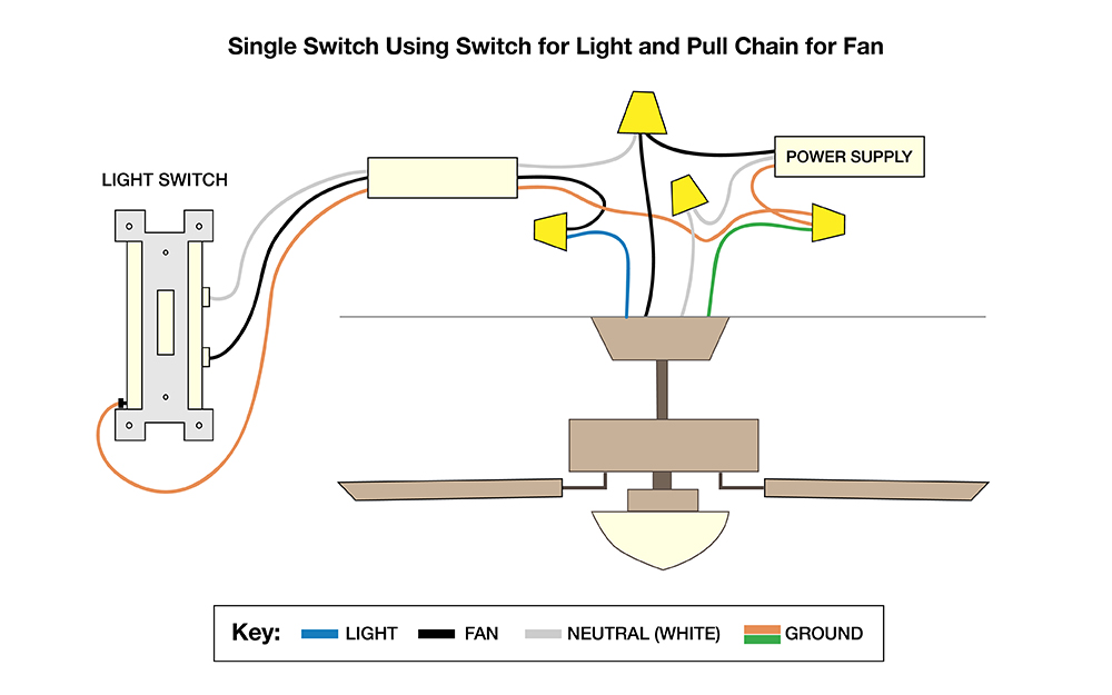
Twist the copper ends of the black and blue wires together like you did with the previous wires. The cooling switch also sold in a universal format is used to trigger the relay coil and. Hayden flex a lite or perma cool brands can provide a 12 volt output when activated. Using the switch to control the light then turning onoff the fan from the fan itself.
A single 2 way switch turns onoff both light fan. This will allow you to control your fan and lights with a single switch. Wire a ceiling fan. There will be a cover on the connection box that fastens with a small screw.
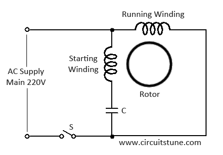
I connect the common wire connection with one connection connector and then i connect the run wire to the other wire connector as i shown in above diagram with blue color line. These fans usually come with a small electrical connection box welded to the side of the housing. Connect the black and blue wires in your fan if you only have 1 switch. Open it pop the plug out of one of the wire holes and thread a wire clamp into it.
In the above ceiling fan capacitor wiring diagram i shown a symbol diagram of fan motor winding in which i shown start run and common wires. Wiring diagram for a bathroom exhaust fan. Suggested electric fan wiring diagrams suggested primary cooling fan single speed onoff using 12 volt switching devices only for primary activation note. To wire an exhaust fan to a wall switch use this diagram.
Most stand alone adjustable thermostats ie. This diagram is for those who are replacing a light fixture with a ceiling fan. Made of silicon electrical steel sheets and filled with prime quality aluminum alloy rotor is the rotating part of the fan motor. The hot from the source is connected to the common on sw1 and the neutral is spliced through to the ceiling box using the white cable wire.
This would be a new circuit ran to the ceiling fan.
How To Wire A Ceiling Fan The Home Depot
Ceiling Fan Wiring Diagram Switch Loop

Ceiling Fan Switch Wiring Electrical 101
Ceiling Fan Wiring Diagram
Ceiling Fan Switch Wiring Electrical 101
Wiring Diagrams For A Ceiling Fan And Light Kit Do It

Ceiling Fan Wiring Diagram Ceiling Fan Ceiling Fan Wiring
Ceiling Fan Wiring Diagram With Capacitor Connection
How To Wire A Ceiling Fan The Home Depot
Wiring Diagrams For A Ceiling Fan And Light Kit Do It
Dual Fan Wiring Diagram

Cooling Fans Wiring Diagram

Extractor Fan Wiring Diagram In 2019 Ceiling Fan Switch
Ceiling Fan Wiring Diagram Single Switch
Wiring Diagrams For A Ceiling Fan And Light Kit Do It

Ceiling Fan Switch Wiring Electrical 101

Fan Limit Control Installation Faqs

4 Speed Fan Wiring Diagrams Wiring Schematic Diagram
