Logic Gates Circuit Diagram
Digital Electronics Logic Gates Basics Tutorial Circuit

Combinational Logic Circuits Using Logic Gates Circuit

Basic Logic Gates With Truth Tables Digital Circuits
It can also be done using nor logic gates in the same way.
Logic gates circuit diagram. Take a look. This article explains the basic logic gates like not gate and gate or gate nand gate nor gate exor gate and exnor gate with their corresponding truth tables and circuit symbols. Basic logic gates what is logic gate. An example of a combinational circuit is a decoder which converts the binary code data present at its input into a number of different output lines one at a time producing an equivalent decimal code at its output.
By dilip raja sep 11 2015 0. Logic gates and circuit simplification tutorial cslearning101. Logic gates truth tables. In this instructable we will talk about a few of the simplest of these devices and see some of the fun things you can do with them.
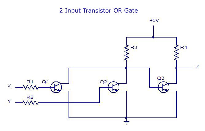
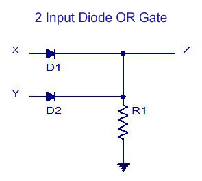
The output of the x or gate will be the sum of the modulo sum of its inputs. Logic gates are considered to be the basics of boolean logic. A logic gate is a basic building block of a digital circuit that has two inputs and one outputthe relationship between the ip and the op is based on a certain logic. These gates are implemented using electronic switches like transistors diodes.
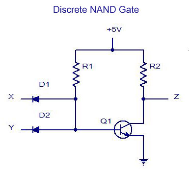
The outputs of all nand gates are high if any of the inputs are low. Simple logic gates and circuits. In electronics a not gate is more commonly called an inverter. This is a not and gate which is equal to an and gate followed by a not gate.
These logic gates are the building blocks of combinational logic circuits. So what are logic gates. Explore digital logic circuits with. Digital logic implementing a logic circuit from a boolean expression.
And logic gate is a digital logic gate designed for arithmetic and logical operations every electronic student must have studied this gate is hisher career. Circuit diagram and. When both the inputs assume the logic 0 state or when both the inputs assume the logic 1 state the output assumes a logic 0 state. The diagrams below show two ways that the nand logic gate can be configured to produce a not gate.
On a circuit diagram it must be accompanied by a statement asserting that the positive logic convention or negative logic convention is being. The circle on the symbol is called a bubble and is used in logic diagrams to indicate a logic negation between the external logic state and the internal logic state 1 to 0 or vice versa. X or gate assumes logic 1 state when any of its two inputs assumes a logic 1 state. An x or gate is a two input one output logic circuit.
From simple gates to complex sequential circuits plot timing diagrams automatic circuit generation explore standard ics and much more for free. The symbol is an and gate with. This gate is mainly used in applications where there is a need for mathematical calculations.

Logic Or Gate Tutorial With Logic Or Gate Truth Table
Digital Electronics Logic Gates Basics Tutorial Circuit
And Gate Circuit Diagram Working Explanation

3 Logic Circuits Boolean Algebra And Truth Tables Dr
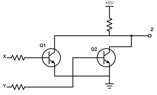
Digital Electronics And Logic Circuits Role Of Transistors
Digital Electronics Logic Gates Basics Tutorial Circuit
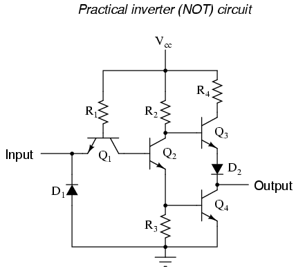
The Not Gate Logic Gates Electronics Textbook

Digital Logic Gate Tutorial Basic Logic Gates

Transistor Logic Not Gate Inverter
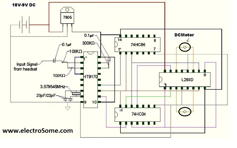
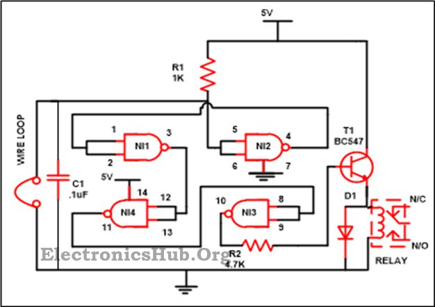
Cell Phone Controlled Land Rover Using Logic Gates
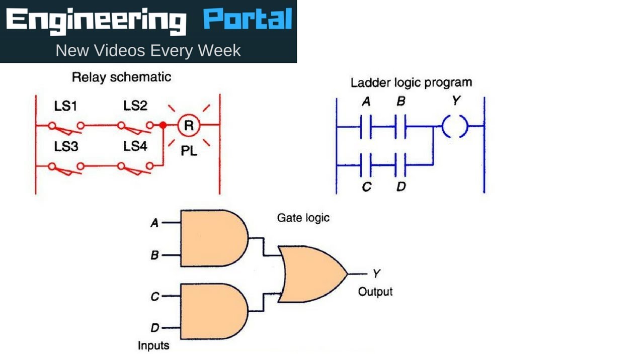
Logic Gates Vs Ladder Logic Circuits
Luggage Security Alarm Project Circuit Using Logic Gates
Digital Electronics And Logic Circuits Role Of Transistors

Combinational Circuit Logic Gate Diagram
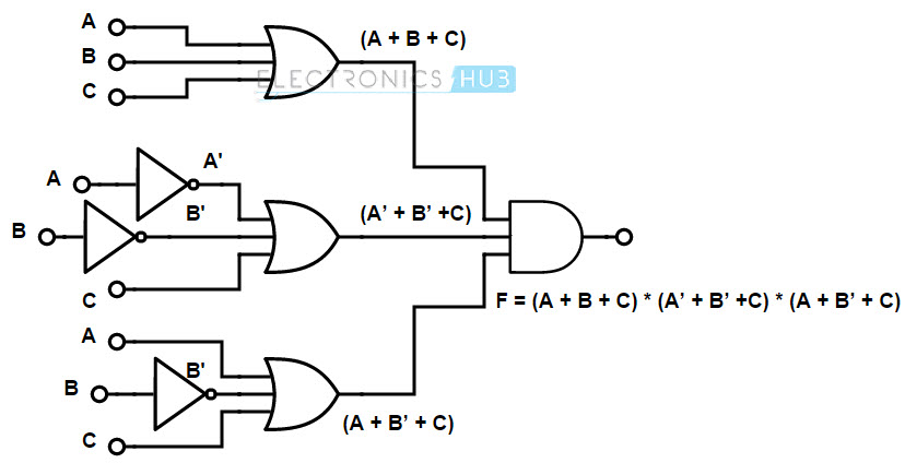
Boolean Functions Using Logic Gates
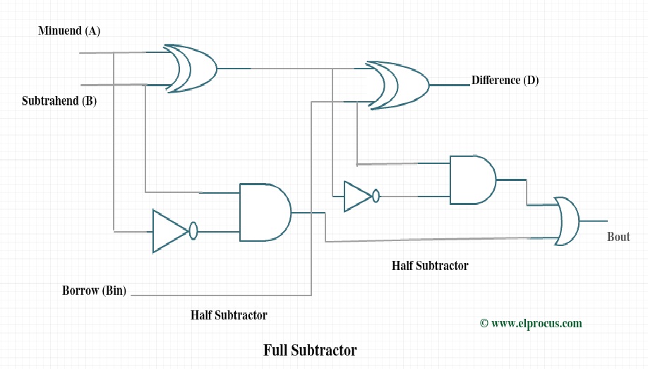
Full Subtractor Circuit Design Theory Truth Table K Map

Logic Circuits Computer Science Gcse Guru
Introduction To Logic Gates Not And Nand Or Nor
