Outlet Installation Diagram

Wiring Diagram For A Grounded Duplex Receptacle Diy
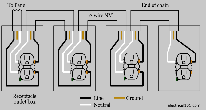
Outlet Wiring Electrical 101
Wall Outlet Wiring Diagram

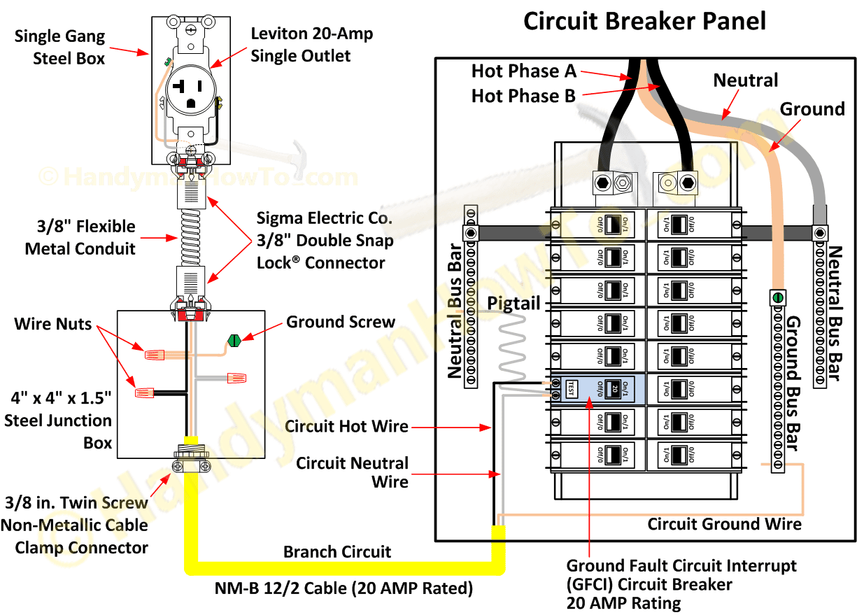
This wiring diagram illustrates installing a 15 amp circuit breaker for a 120 volt branch circuit.
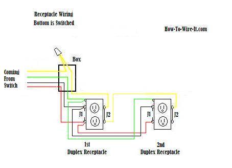
Outlet installation diagram. This wiring is commonly used in a 20 amp kitchen circuit where two appliance feeds are needed such as for a refrigerator and a microwave in the same location. The hot black wire should connector to the brass colored screw. The black wire line and white neutral connect to the receptacle terminals and another 2 wire nm that travels to the next receptacle. Wiring diagram for dual outlets.
A 15 amp circuit is usually used for wall receptacle outlets and room light fixtures. Wiring a gfci outlet and a light switch. This receptacle has a ground connection not found in the older 30 amp circuit for added protection against electrocution. Steps to take when wiring the electrical outletreceptacle.
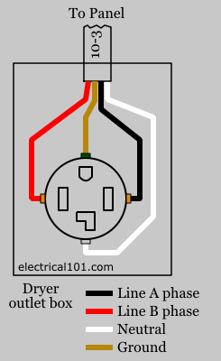
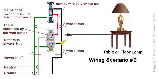
Electrical wiring for a switch outlet combination. This circuit is used for a new clothes dryer outlet installation. Standard wall outletreceptacle wiring. This diagram illustrates wiring a gfci receptacle and light switch in the same outlet box a common arrangement in a bathroom with limited space.
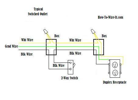
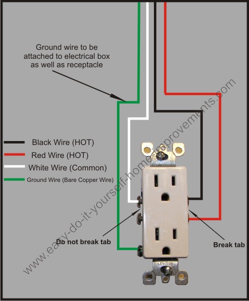
Here 3 wire cable is run from a double pole circuit breaker providing an independent 120 volts to two sets of multiple outlets. Wiring diagram for a 30 amp dryer outlet. This diagram shows the wiring for multiple switched outlets on one switch. The source for the circuit is at the switch and 2 wire cable runs to each receptacle outlet.
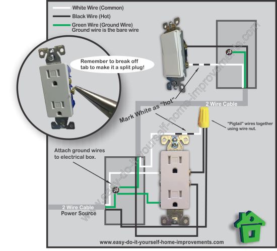
The neutral wire from the circuit is shared by both sets. At the outlets each is wired using a pigtail splice to make the hot and neutral connections. How to install electrical outlet and switch combo wiring in most cases the primary power source is shared between the switch and the outlet either with a wire jumper or the bridge or tab that is located on the side of the combo switch and outlet. When wiring a wall outlet the neutral white wire should connect to the white or silver metal screw.
Now some electricians will use a 1wire jumper from the outlet and wire nut together the circuits inside the box but. Wiring for a switch and gfci receptacle in the same box is also shown. Wiring diagram for multiple switched outlets. The 142 awg cable for this circuit includes 2 conductors and 1 ground wire.
To wire a gfci circuit breaker see this link and wire a gfci switch combo at this link. This repeats until the end of the chain. The green screw obviously ties to the bare ground wire. This is a newer version of the outdated 30 amp receptacle appearing in the previous diagram.
Wiring a combo switch outlet. How to wire an electrical outlet wiring diagram wiring an electrical outlet receptacle is quite an easy jobif you are fixing more than one outlet the wiring can be done in parallel or in series.

Double Outlet Box Wiring Diagram In The Middle Of A Run In
Wiring Diagrams For Electrical Receptacle Outlets Do It
Wiring Diagrams For Electrical Receptacle Outlets Do It
Wire An Outlet
Outlet Wiring Electrical 101
Wire An Outlet
Switched Outlet Wiring Diagram
Wiring Diagrams For Electrical Receptacle Outlets Do It

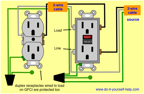
Gfci Outlet Wiring Diagram In 2019 Outlet Wiring Home

Wiring A Gfci Outlet How To Wire Line And Load Schematics
How To Wire An Electrical Outlet Under The Kitchen Sink

Wiring A Switched Outlet Wiring Diagram Electrical Online
How To Wire A Switched Outlet With Wiring Diagrams
Split Plug Wiring Diagram

Wiring A Gfci Outlet With Diagrams Pro Tool Reviews
Installing Wall Outlet Customer Support

Failures In Outlet Testing Exposed Electrical Construction

Wiring A Switched Outlet Wiring Diagram Power To
