Pressure Transmitter Diagram
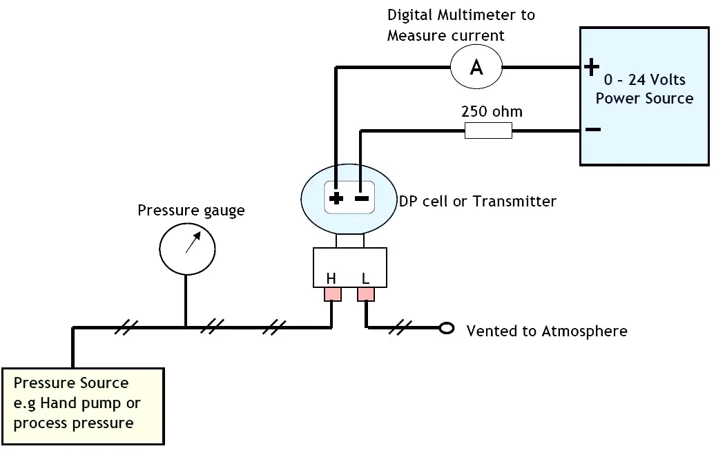
Differential Pressure Transmitter Calibration Procedure
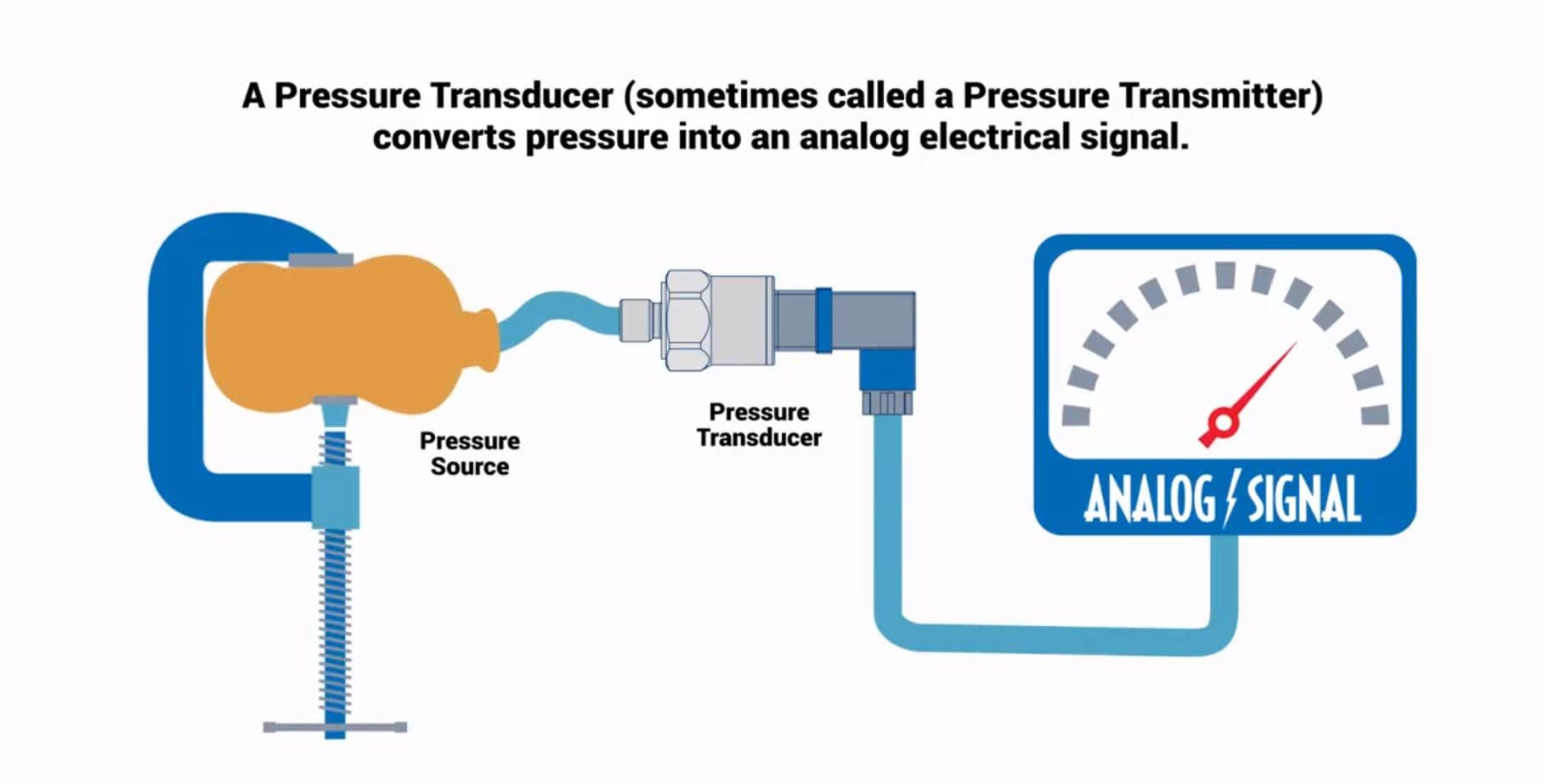
How Do Pressure Transducers Work Omega Engineering

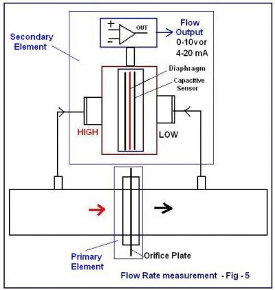
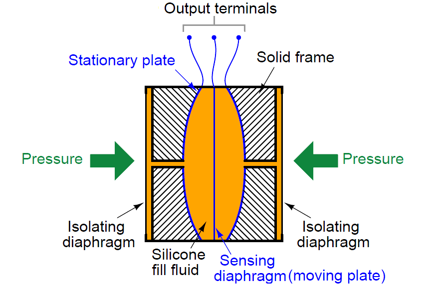
Capacitance Pressure Transmitter Instrumentation And
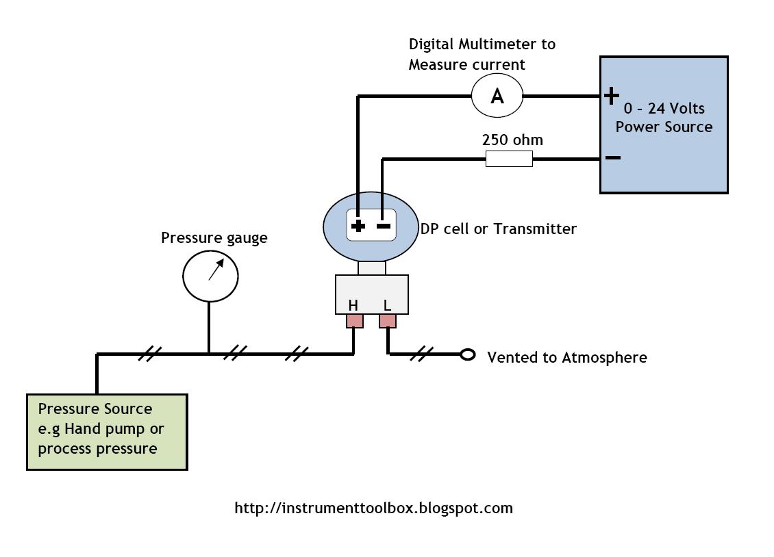
This will generate a voltage drop of between 1 and 5 volts which is directly proportional to the 4 20ma signal.
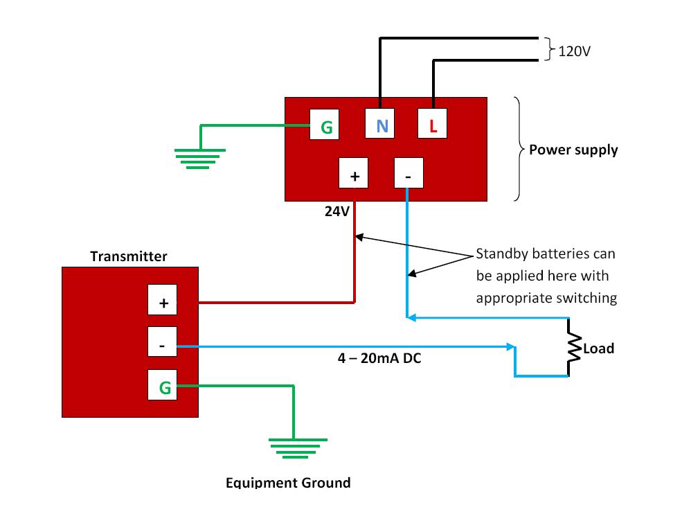
Pressure transmitter diagram. The 4 20ma signal flows through the 24v dc line and the signal line to the controller. The most common and useful industrial pressure measuring instrument is the differential pressure transmitter. It so happens that on some vehicles cadillacs the high pressure sensor is connected to the other sensor voltage reference line. An introduction to dp transmitters.
The figure above shows the wiring diagram of the four wire transmitter. Pressure transmitters wire configuration. Pressure transmitters and transducers with industry leading performance help improve operations in a wide range of industries gain the process insight to optimize every point with over 50 years of experience rosemount paine and roxar pressure instrumentation provide solutions to critical measurement challenges even in the harshest environments. The transmitter and control panel can use the same 24v and 0v dc supply lines.
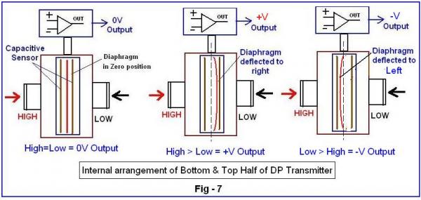
The industrial differential pressure transmitters are made of two housings see fig 6. One of these ports is labelled high h and the other is labelled low. Most of the power supply is ac 220v and some are dc 24v. How to connect a 4 20ma current loop pressure transmitter.
The rugged design provides resistance to vibration shock wide temperature variations rfi and other extreme environmental conditions that are typical of industrial and oem applications. The wika a 10 pressure transmitter is precision engineered and manufactured to fit many industrial and oem pressure measurement applications. Some also have ma and mv signals but the load resistance or input resistance. B the electronics for converting differential pressure into a standard 4 20ma dc signal the pressure sensing ports on the transmitters typically have 14 inch female npt threads to readily accept connection to the process medium.
Current source transmitter non isolated 3 wire this is the most common configuration of modern 4 20ma transmitters. In the transmitter wire configurations discussed above it is assumed that a voltage signal range of 1 5v and a standard current signal of 4 20ma are used. If the input device only includes a voltage input it can be easily adapted to measure a 4 20ma signal by adding a 250 ohm load resistor across the positive and negative input connections. If the voltage range is 1 5 volts and the current range is 4 20 ma the precision resistor value must be 250 ohms.
Dc4 20 ma output signals and the load resistance is 250 w or dc0 10 ma load resistance to 0 15 k w. Rosemount 3051 pressure transmitter and rosemount 3051cf series flow meter with 4 20 ma hart and 1 5 vdc low power protocol.
Beginner S Guide To Differential Pressure Transmitters
Pressure Transmitters Wire Configuration Learning
How To Calibrate Your Dp Transmitter Learning

Optical Pressure Sensor Working Construction Circuit Diagram

Diaphragm Pressure Transducer Working Types Capsules

Pressure Transducers And Transmitters

Pressure Sensors The Design Engineer S Guide Avnet Abacus
Beginner S Guide To Differential Pressure Transmitters
Differential Pressure Transmitter Working Principle
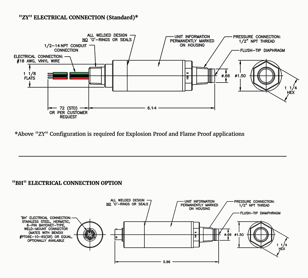
Model 570 Flush Tip Diaphragm Pressure Transmitter
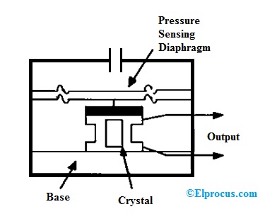
Pressure Transducer Circuit Diagram Types And Its

Pressure Transducers And Transmitters

Working Of Differential Pressure Transmitter

Diaphragm Seal Wikipedia

Pressure Sensors The Design Engineer S Guide Avnet Abacus
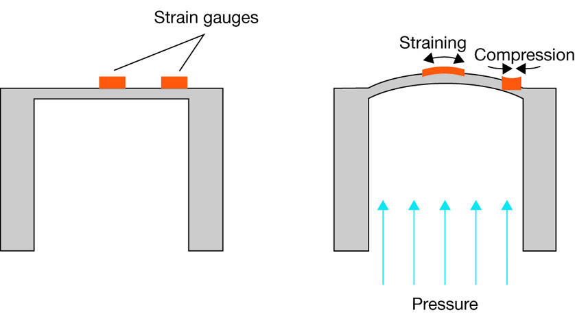
What Is The Functional Principle Of A Resistive Pressure
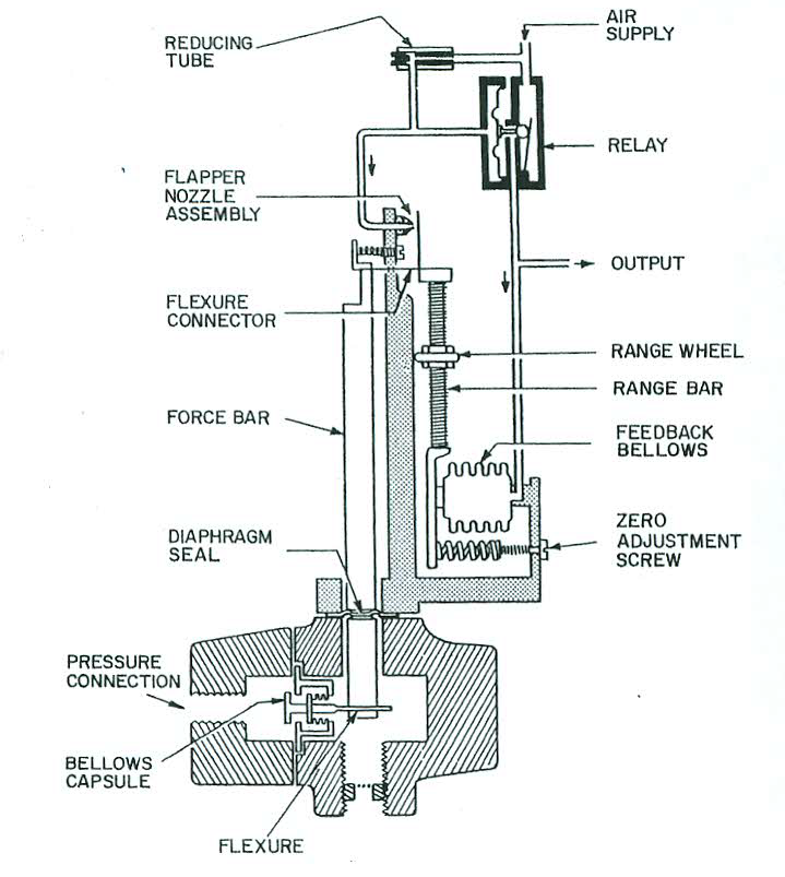
How A Pneumatic Pressure Transmitter Works Learning
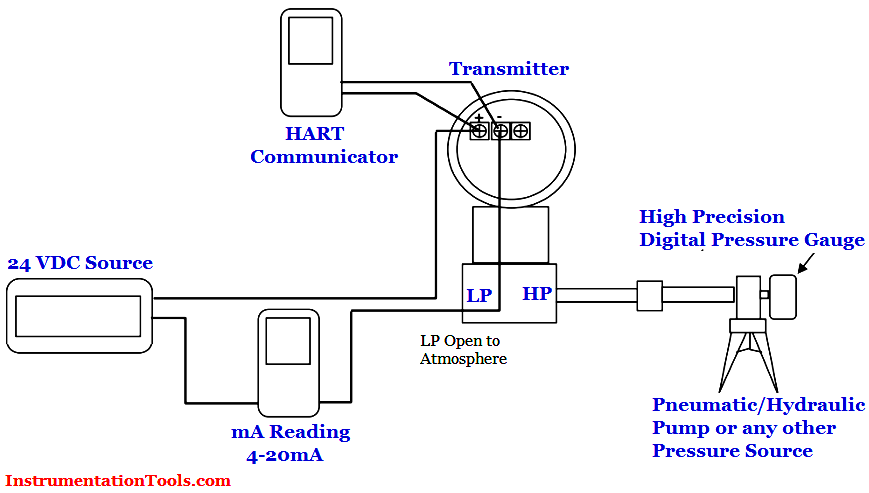
Differential Pressure Transmitter Calibration Procedure
