Schematic Control Diagram

Visual Walkthrough Of Schematic Diagram And Control Logic
Basic Wiring For Motor Control Technical Data Guide Eep

Types Of Motor Control Schematics Info Mechanics Pics Non

But it does tend to become more complex.
Schematic control diagram. Duplex pump control panel wiring diagram wire center. A wiring diagram is a sort of schematic which makes use of abstract photographic signs to show all the affiliations of elements in a system. Pump control panel wiring diagram schematic collections of pump control box wiring diagram get free image about wiring diagram. Duplex pump control panel wiring diagram awesome nih standard cad.
This circuit control diagram template offers plenty of circuit diagram symbols. Learn how to explain each component in regards to controlling logic. A control flow diagram can consist of a subdivision to show sequential steps with if then else conditions repetition andor case conditions. Schematic diagrams show components in their electrical sequence without regard for physical location.
You can use it as a start template to draw circuit control or electrical schematic diagrams. Schematic diagrams are used to troubleshoot and install control circuits. Three phase motor power control wiring diagrams 3 phase motor power control wiring diagrams three phase motor connection schematic power and control. Diesel engine fire pump controller wiring diagram new diesel.
Figure 5 below shows a schematic diagram for a plc based motor control system similar to the previous motor control example. When including a plc in the ladder diagram still remains. I want star delta power and. Based on your observations of these two diagrams explain how electromechanical relays are represented differently between ladder and schematic diagrams.
Scheme it is a free online schematic drawing tool that will allow you to produce professional looking schematic diagrams add corresponding part numbers and share your schematic with others. We have new features. This figure shows the e stop wired to cutoff power to all of the devices in the circuit including the plc. Also explain the operation of this motor control circuit.
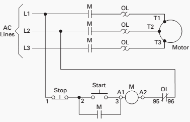
Interpret this ac motor control circuit diagram explaining the meaning of each symbol. Three phase motor power control wiring diagrams 3 phase motor power control wiring diagrams three phase motor connection schematic power and control. Schematic diagrams are used to troubleshoot and install control circuits. Icons that stand for the parts in the circuit as well as lines that stand for the connections between them.
Suitably annotated geometrical figures are used to represent operations data or equipment and arrows are used to indicate the sequential flow from one to another.

Flowchart Schematic Diagram For The Control Circuit Of A

How To Construct Wiring Diagrams Industrial Controls

Electrical Schematic Diagram For The Control Circuit Of A

Schematic Diagram Of The Flow Control Valve Download

Ac Motor Control Circuits Worksheet Ac Electric Circuits

Figure Fo 4 Motor Control Cca A2 Schematic Diagram
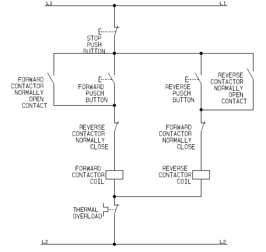
Circuit Breaker Control Schematic Explained

Schematic Diagram Of Feedback Control System Download
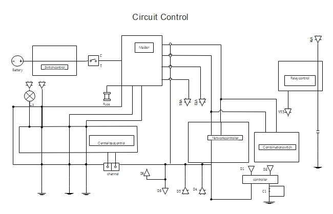
Circuit Control Diagram Free Circuit Control Diagram Templates
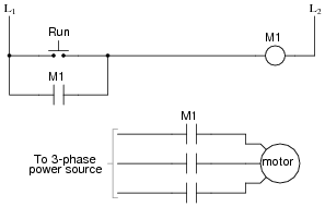
Ac Motor Control Circuits Worksheet Ac Electric Circuits
Control Panel Wiring Diagrams Wiring Schematic Diagram
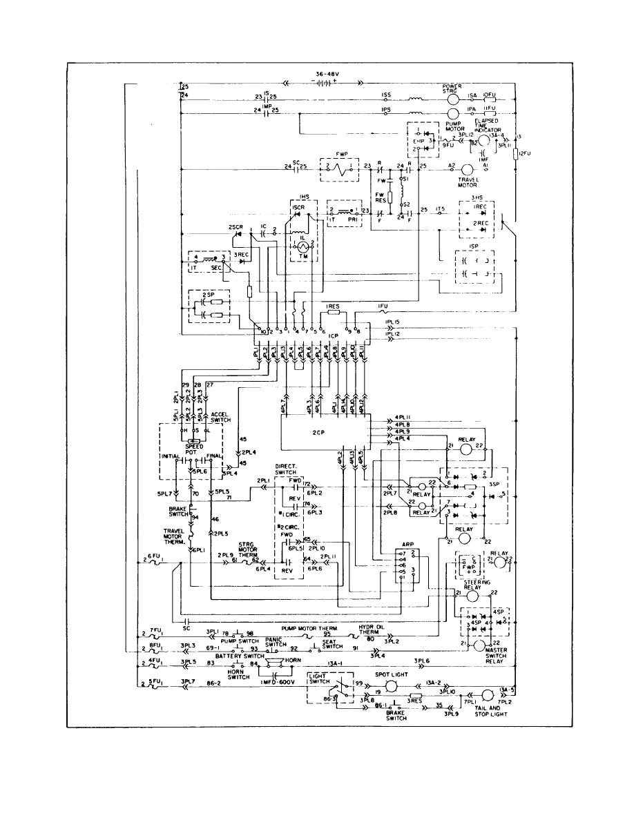
Figure 4 1 Control Panel Circuit Schematic Diagram
Flowchart Schematic Diagram For The Control Circuit Of A

User Guide 4 4 Specifying Schematic And System Diagram Options
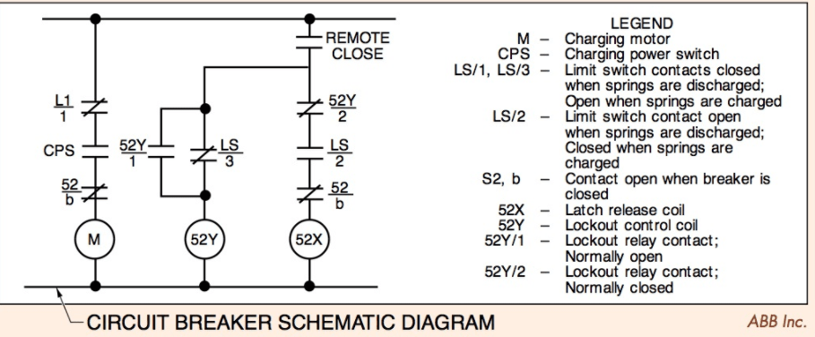
Circuit Breaker Schematic Diagram Electrical Academia
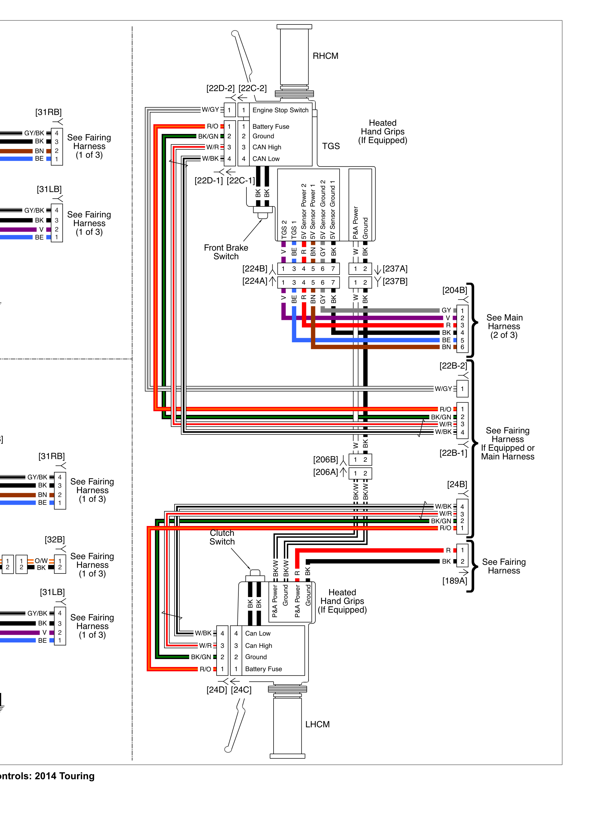
Right Hand Controls Schematic Harley Davidson Forums

Kc 2616 Ps3 Wireless Controller Remote Control Unit
How To Read A Schematic Learn Sparkfun Com
