Schematic Diagram Of Water Pump
Water Pump Controller Detailed Circuit Diagram Available

Schematic Diagram Of The Pilot Unit 1 Feed Water Tank 2

Circuit Diagram Of Water Pump Control System Download
Wiring diagram for water pump pressure switch fresh water pump.
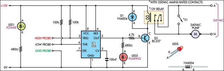
Schematic diagram of water pump. A wiring diagram is a sort of schematic which makes use of abstract photographic signs to show all the affiliations of elements in a system. Icons that stand for the parts in the circuit as well as lines that stand for the connections between them. The information provided here is for educational purposes only. Technically qualified personnel should install pumps and motors.
The pump is powered by an electric motor that drives an impeller or centrifugal pump. A pump that has a switch that is integral to the pump cannot be adjusted to allow for more or less water to enter the sump pit. Chilled water schematic and condenser water schematic how to read and understand the engineering drawings with real world examples illustrations animations and video tutorial. The impeller moves water called drive water from the well through a narrow orifice or jet mounted in the housing in front of the impeller.
Variety of water pump pressure switch wiring diagram. Diagrams typical pump installations. Click on the image to enlarge and then save it to your computer by right clicking on the image. The only adjustment available for pumps provided with this type of switch is how high or low the pump is installed inside the pit.

Water Pump Relay Controller Circuit Schematic Eeweb Community
Water Pump Relay Controller Circuit Schematic Circuit Diagram

Adding A Soft Start To Water Pump Motors Reducing Relay
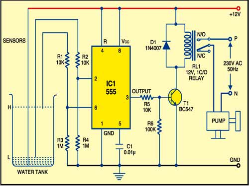
Automatic Water Pump Controller Full Circuit Available

The Citizen Journals Schematic Diagram On The Proper Use Of

Schematic Diagram Of Solar Water Pumping System Download

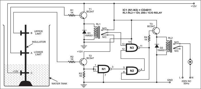
Automatic Water Pump Controller Circuit Diagram

The Citizen Journals Schematic Diagram On The Proper Use Of

Schematic Diagram Of Feed Water Pump With Application Of Vsd

Water Pump Controller Circuit Full Project Details Available
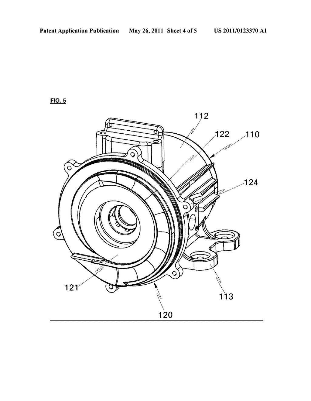
Electric Water Pump Diagram Schematic And Image 05

Schematic Diagram Of The Heat Pump Download Scientific Diagram

Air Cooler Water Pump Guard
Cheap Pump Controller Circuit Diagram

Water Pump And Water Pump System And Method Diagram

Schematic Diagram Of The Experimental Apparatus 1 Water

Shurflo Pump Wiring Diagram Wiring Schematic Diagram

Automatic Water Control With Auto Shut Down Water Pump
