Wiring A Set Of Schematic
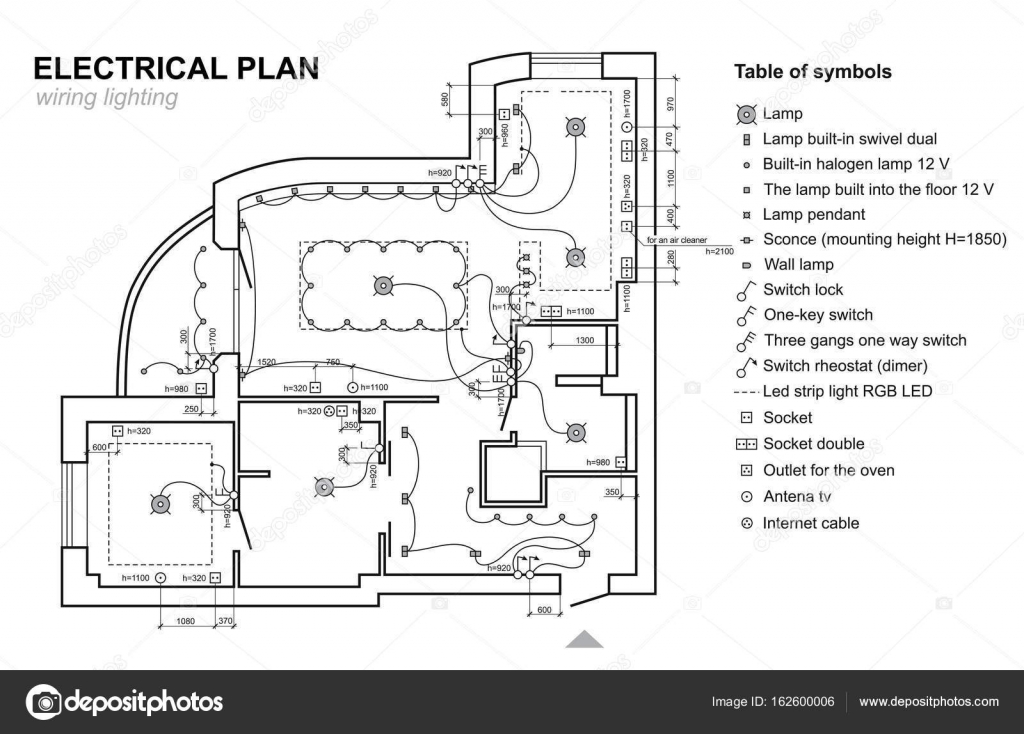
Plan Wiring Lighting Electrical Schematic Interior Set Of
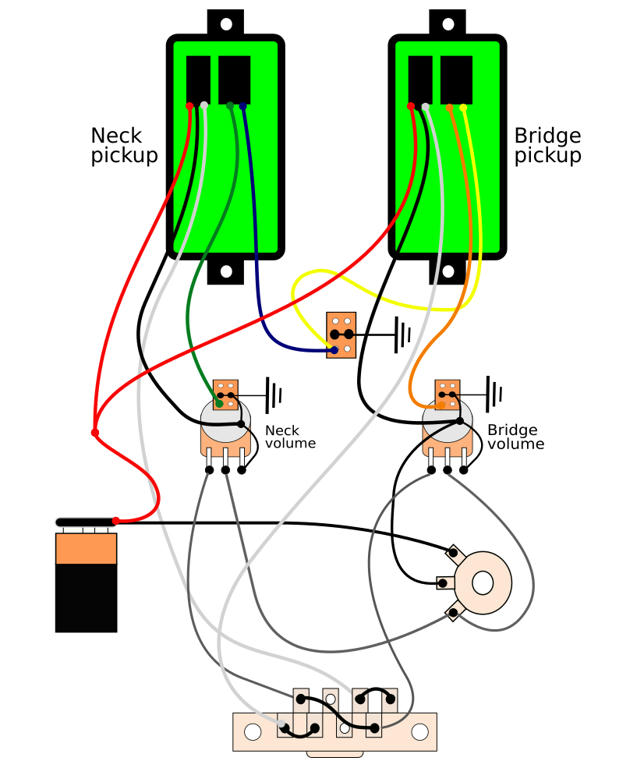
Help Needed Wiring Schematic For Fishman Kse Set

Wiring Schematic Set For New Single Fuse Box Wiring Kit

A wiring diagram is a simplified conventional pictorial representation of an electrical circuit.
Wiring a set of schematic. This might seem intimidating but it does not have to be. Interested in a 4 way switch wiring diagram. Below is the generic schematic of how the wiring goes. Using the same example as above the wiring diagram includes r1 from the schematic but instead of being on the far left it is depicted in the middle which is its actual location on the circuit board.
Purchase full set of wiring diagrams. In this case you will need a set of wiring taps and a pair of pliers. A wiring diagram is a simple visual representation of the physical connections and physical layout of an electrical system or circuit. A wiring diagram usually gives information about the relative position and arrangement of devices and terminals on the devices to help in building or servicing the device.
It shows how the electrical wires are interconnected and can also show where fixtures and components may be connected to the system. 4 pin trailer wiring diagram. The reason for this is simple. Purchase full set of wiring diagrams for 1995 full wiring diagrams by mitchell1 not only do you gain online access to full system wiring diagrams but you will also have access to the entire auto repair manual.
Wiring diagrams for circuits use the same labels as the schematic. It shows the components of the circuit as simplified shapes and the power and signal connections between the devices. This is unlike a schematic diagram where the arrangement of the components interconnections on the diagram us. Step by step solar panel installation tutorials with batteries ups inverter and load calculation.
We recommend these standards because they are pretty universal. Switch loop dimmer switched receptacles a switch combo device two light switches in one box and more. The following trailer wiring diagrams and explanations are a cross between an electrical schematic and wiring on a trailer. To connect the electric system of your trailer to the vehicle you will be using special connector.
Wiring diagrams for light switches numerous diagrams for light switches including. Wiring diagrams for receptacle wall outlets diagrams for all types of household electrical outlets including. All about solar panel wiring installation diagrams. The basics of home electrical wiring diagrams.
Pick the diagram that is most like the scenario you are in and see if you can wire your switch. That said for specific situations there are industrial standards with different connectors and wire arrangements. Wiring diagrams device locations and circuit planning a typical set of house plans shows the electrical symbols that have been located on the floor plan but do not provide any wiring details. Above we have describes the main types of trailer wiring diagrams.
Duplex gfci 15 20 30 and 50amp receptacles.

A Schematic Diagram Of The Experimental Set Up B Wiring
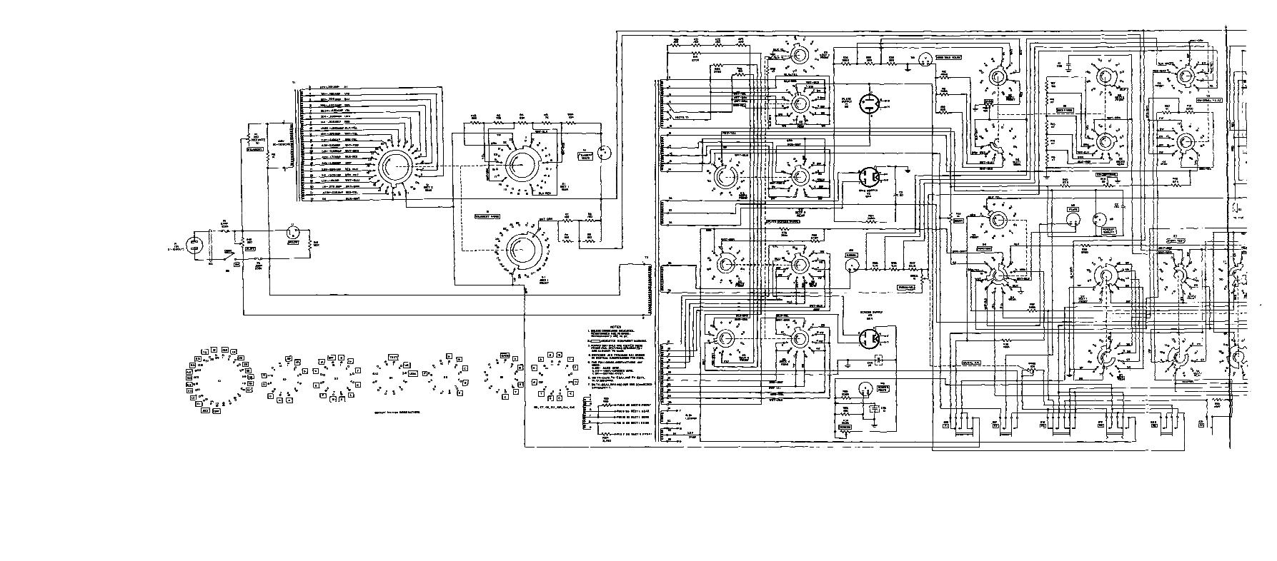
Figure 26 Test Set Electron Tube Tv 2 U Schematic Diagram
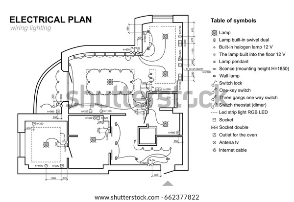
Plan Wiring Lighting Electrical Schematic Interior Stock
Plan Wiring Lighting Electrical Schematic Interior Set Of Standard
Plan Wiring Lighting Electrical Schematic Interior Stock
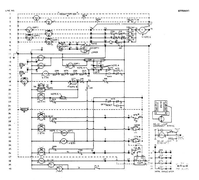
Control Panel Wiring Schematic

Telephone Technical References
1974 Bronco Wiring Diagram Schematics Online

Plan Wiring Lighting Electrical Schematic Interior Set Of

Plan Wiring Lighting Vector Photo Free Trial Bigstock

Experimental Set Up Emg Monitoring Electrodes And Wiring

Generator Wiring Diagram Wiring Schematic Diagram

How To Wire Your Zooz Switch In A 3 Way Configuration Zooz
Wiring A Set Of Outlets Wiring Schematic Diagram 85
Plan Wiring Lighting Electrical Schematic Interior Set Of

Itsy Bitsy M4 Schematic Wiring Diagram Set

Cummins 500 Kva Generator Manual Diesel Spare Parts List 250

Arc Welding Schematic Diagram Wiring Diagrams
