480 Motor Wiring Diagram With Start And Stop
Two Wire Three Wire Motor Control Circuit Motor Control
Stop Start Motor Wiring Diagram Wiring Diagram

Control Wiring 3 Wire Control Start Stop Circuit

Starting a three phase motor.
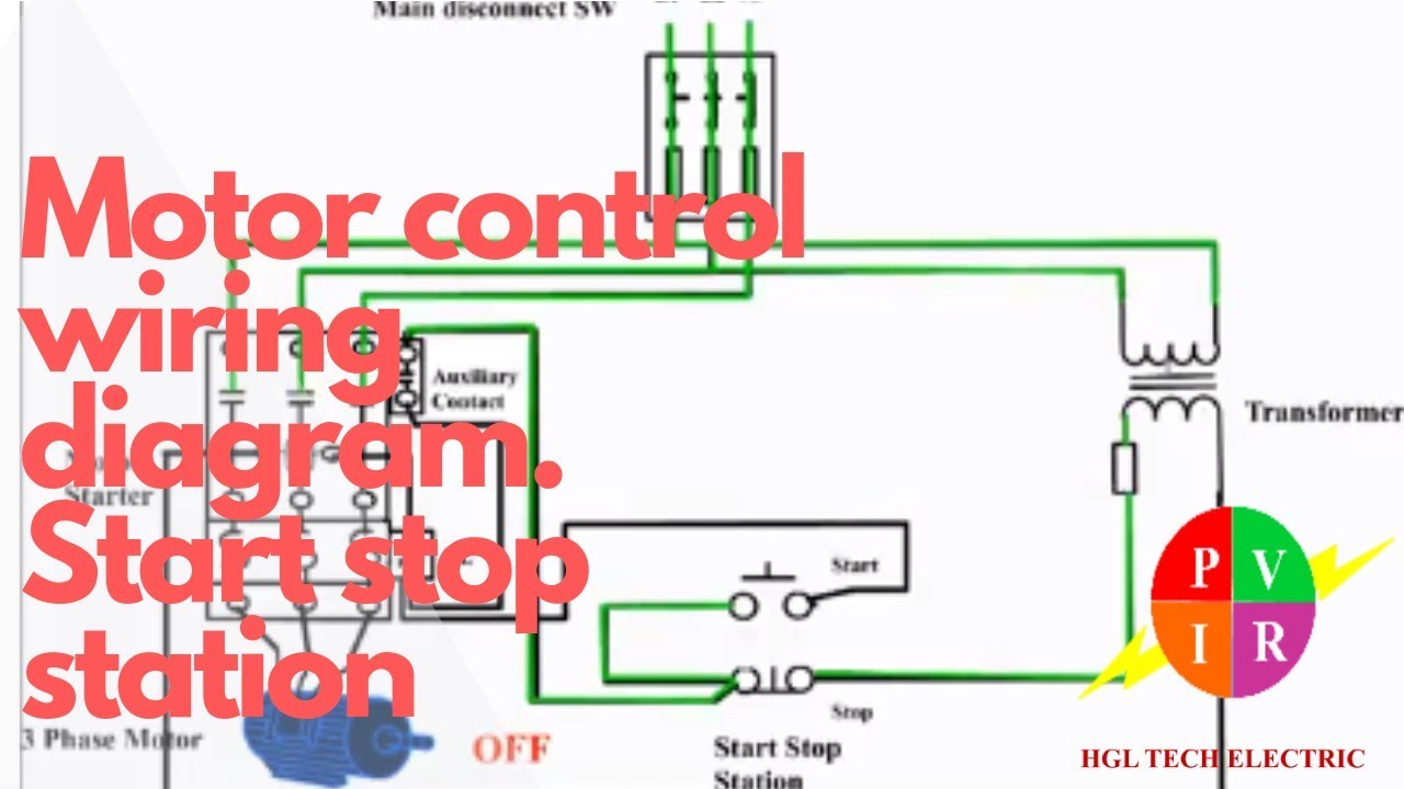
480 motor wiring diagram with start and stop. Basic startstop circuit. When you press the start button and the stop button is not pressed the 24vdc relay energizes and it pulls in the r1 contactor that feeds three phase power to the motor. See image below for an example of 3 wire control being used to pull in a contactor to start a 3 phase motor. Push to make ptm switch use to start the motor and push to brake ptb switch use to stop the motor.
It is not difcult to learn the basic symbols. Wiring diagram single motor with start stop switch basic control motor to get start or stop the motor use a push button switch as a trigger a motor. Pilot light l2 4 2 3 pilot light start stop bulletin 1495 normally closed auxiliary contacts are required. Pressing start immediately sends power through the start pushbutton and the seal in contacting energizing the coil.
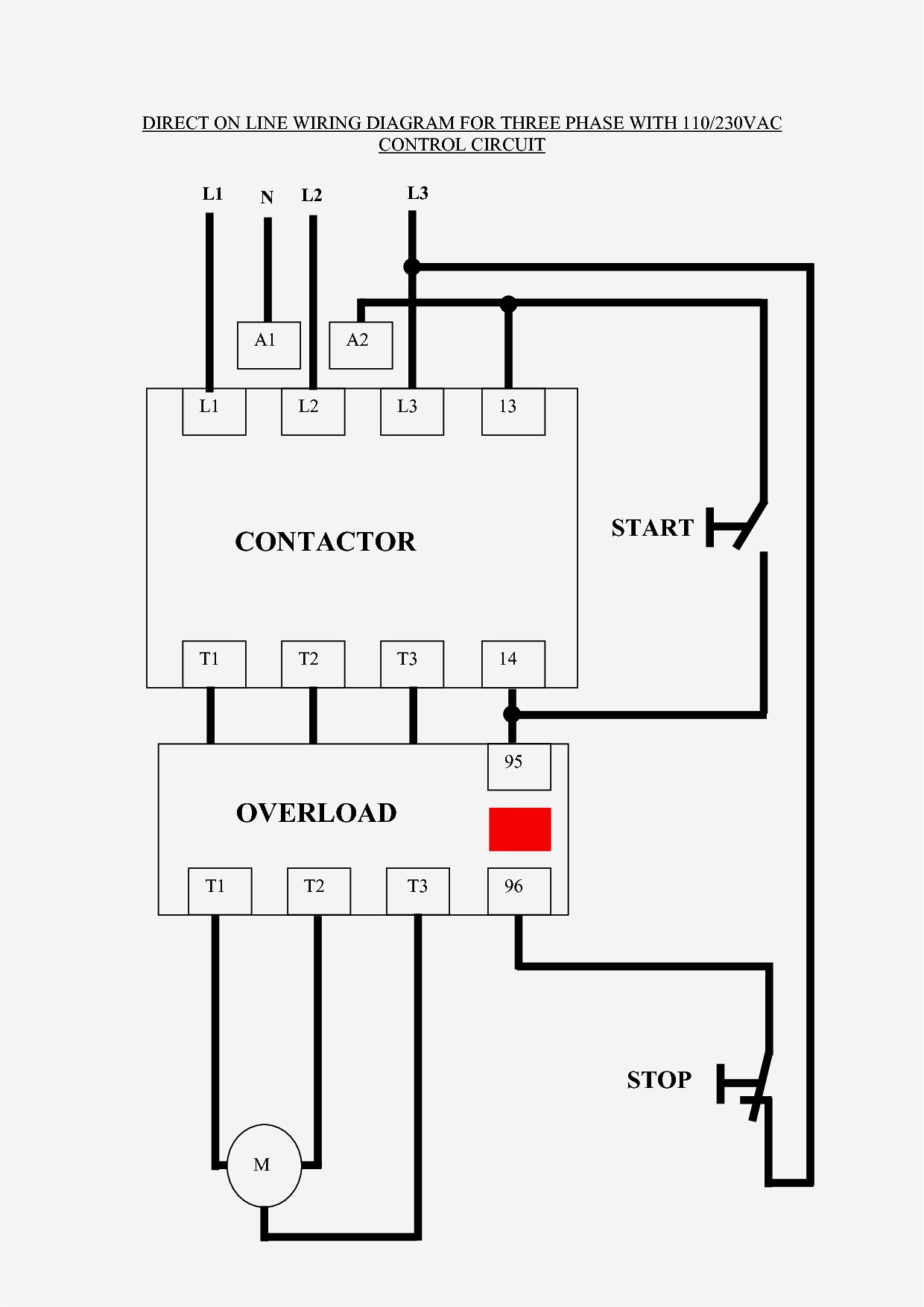
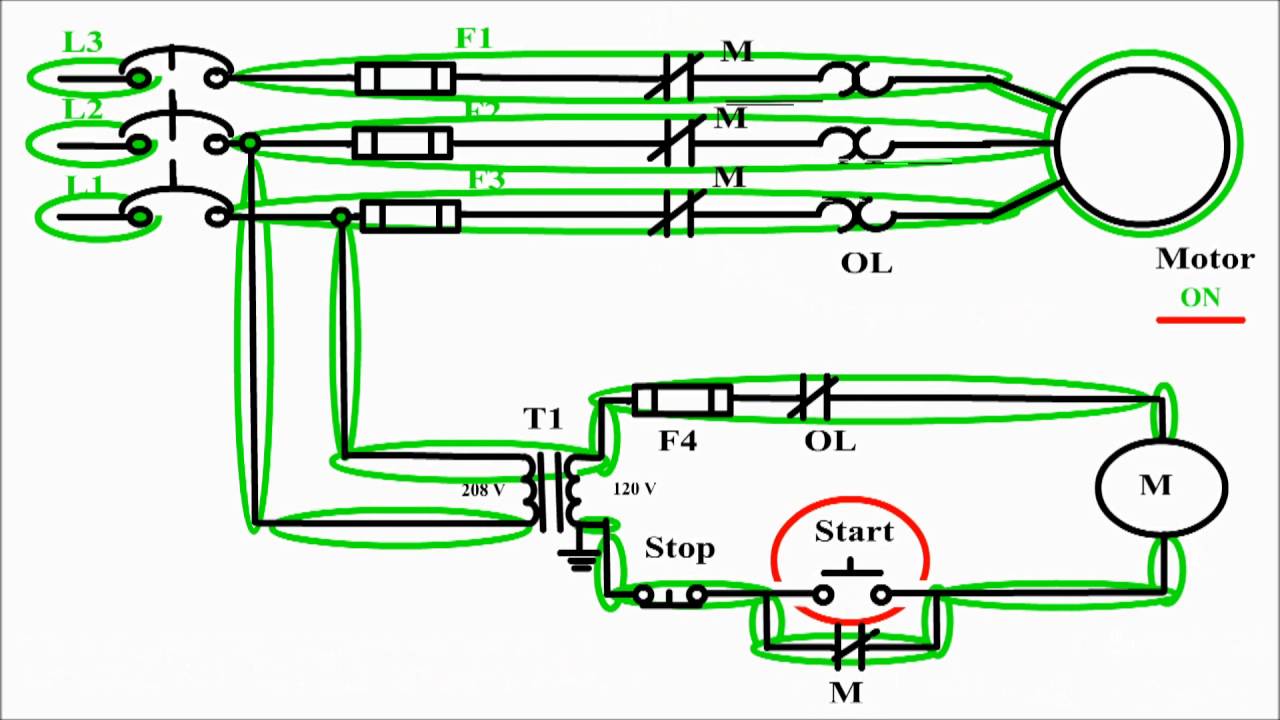
Motor control wiring diagram. Once you do you are able to read diagrams quickly and can often understand a circuit at a glance. Start stop 3 phase motor control wiring diagrams. How to wire a contactor and overload.
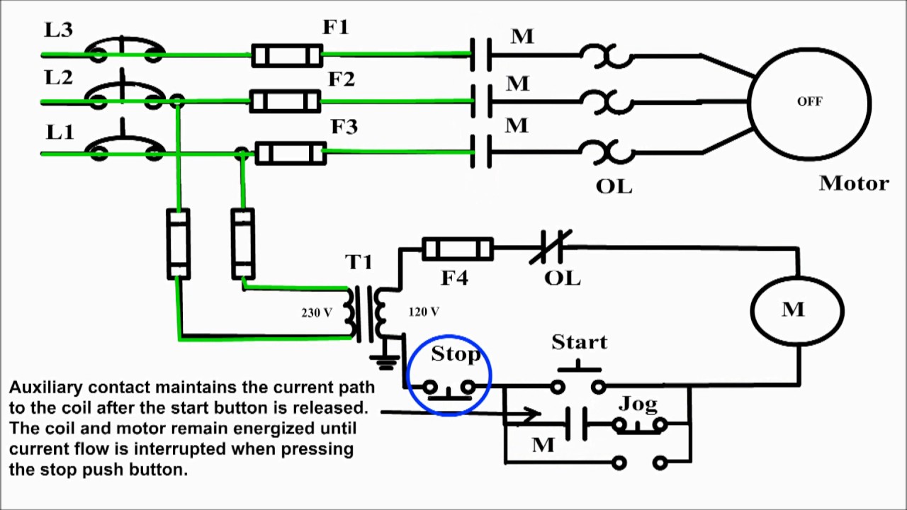
Ladder diagram basics 3 2 wire 3 wire motor control circuit. Enjoy the videos and music you love upload original content and share it all with friends family and the world on youtube. Both line and wiring diagrams are a language of pictures. Start stop 3 wire control.
Whenever we need to start and stop the motor from more than one point then we may expand it through push buttons in the motor control circuit for example you may use this alternative power control wiring diagram of controlling a three phase motor from mo re than two places. The more you work with both line and. Typical wiring diagrams for push button control stations 7 start stop control wiring diagrams single station with motor stopped pilot light l1 start l2 i 1 stop 2 oi 3 n wol. This video explains the basics of a simple start stop motor control circuit.
The most common use of 3 wire control is a startstop control. Motor starter schematic and wiring diagram. With the switch closed the control circuit acts as a normal stopstart station controlling a load connected to the pilot device power is sitting on the start and seal in terminals of the pushbutton. C i m nc.
Motor Control Start Stop Station Motor Control Wiring Diagram How To Wire Start Stop Station
How To Wire A Start Stop Station Controlling A 120 Volt

Start Stop Switch Wiring Diagram Wiring Schematic Diagram

Start Stop Push Button Wiring Diagram For Android Apk Download
Jogging Control Circuit Jog Motor Control Start Stop And Jog
208 3 Phase Motor Wiring Diagram Schematic Wiring Diagram

Practical Machinist Largest Manufacturing Technology Forum

Motor Control Fundamentals Wiki Odesie By Tech Transfer
Basic Wiring For Motor Control Technical Data Guide Eep
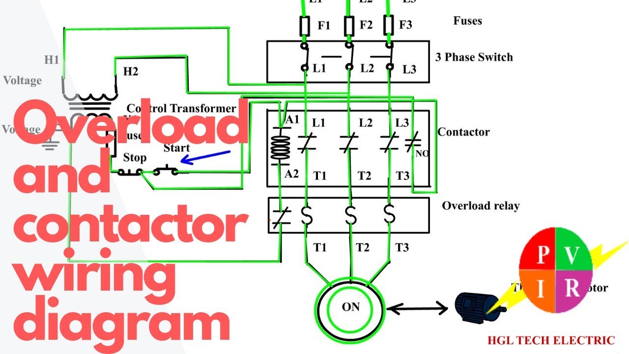
How To Wire A Contactor And Overload Start Stop 3 Phase Motor Control

Start Stop Switch Wiring Diagram Wiring Schematic Diagram

Motor Control Fundamentals Wiki Odesie By Tech Transfer

Electric Contactor Wiring Wiring Schematic Diagram 15

Start Stop Switch Wiring Diagram Wiring Schematic Diagram
Motor Control Circuit Diagram Start Stop 3 Wire Control

Ac Motor Control Circuits Worksheet Ac Electric Circuits
Basic Wiring For Motor Control Technical Data Guide Eep
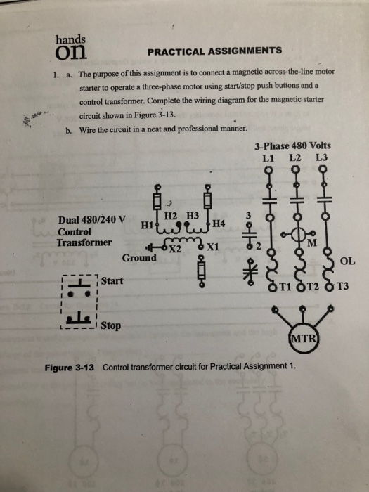
Solved Hands On 1 A The Purpose Of This Assignment Is T
