Car Reverse Horn Circuit Diagram
Car Reverse Horn Circuit Diagram
Musical Car Reverse Horn Circuit Electronic Circuits And
Car Reversing Horn With Flasher Circuit Diagram

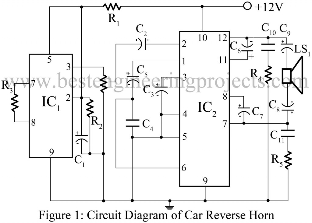
This is a project of a simple car reverse horn circuit.
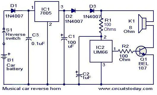
Car reverse horn circuit diagram. Here is a simple circuit that starts playing the car horn whenever your car is in reverse gear. Car reversing horn with flasher here is a simple circuit that starts playing the car horn whenever your car is in reverse gear. This circuit will produce a musical sound when ever your car is in reverse direction to alert the other vehicles. Here is a simple car reverse horn circuit that starts blowing the car horn whenever your car is in reverse gear.
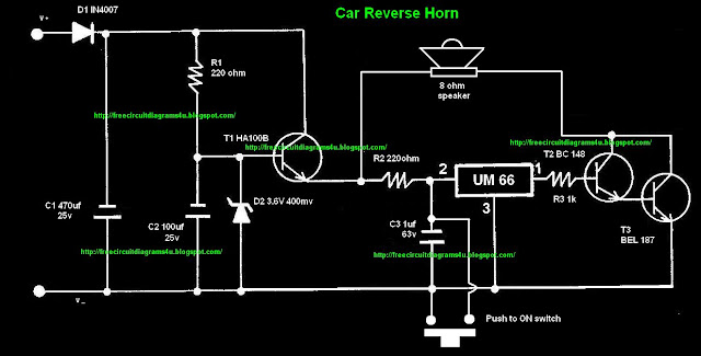
Circuit diagram for car reverse horn circuit diagram of horn system in automobile horns wiring diagram circuit diagram of horn system in automobile hi guys how are you today. Here is a simple circuit that will produce a musical horn when ever your car is in reverse gearthe circuit uses two ics for the operation voltage regulator 7805ic1 and musical tone generator um66ic2. Here is a simple circuit that will produce a musical horn when ever your car is in reverse gearthe circuit uses two ics for the operation voltage regulator 7805ic1 and musical tone generator um66ic2the ic1 reduces the car battery voltage to 5vthe diodes d1 d2 in combination produces an additional drop of 14 v to give a 36 v supply. The circuit is very simple to build and also it is very low power consumption.
Working of the circuit is simple. Produce sound when car is moving in reverse direction. Here is a simple project car reverse horn can be used in car as reverse horn ie. The diodes d1 d2 in combination produces an additional drop of 14 v to give a 36 v supply for the um66.
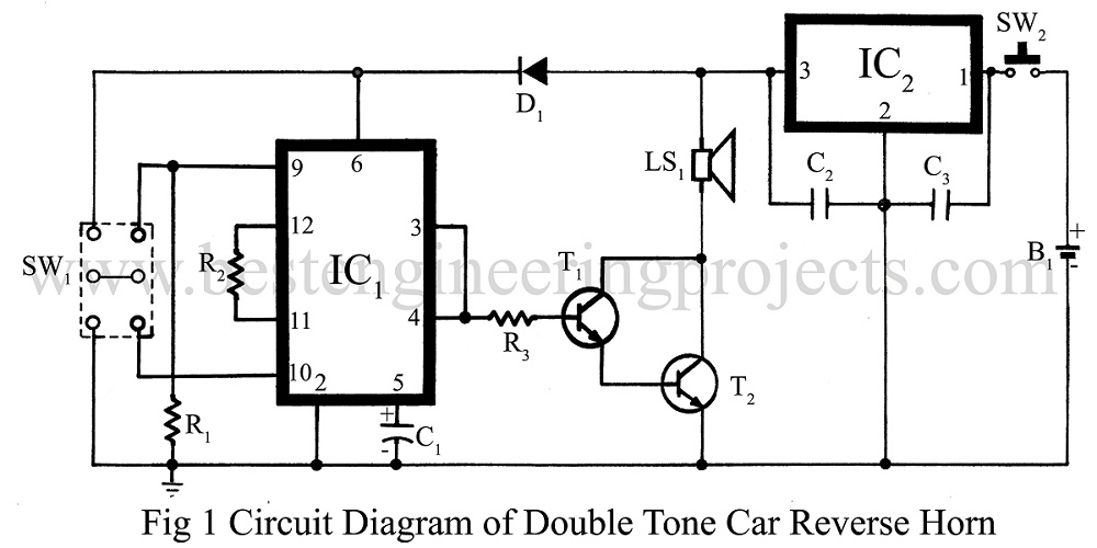
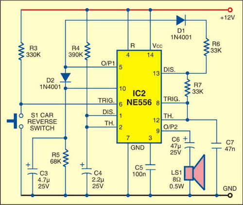
It is followed by amplifier ic ic2 and few other passive components. One of the timers is wired as an astable multivibrator to generate the tone and the other is wired as a monostable multivibrator. The circuit 1 employs dual timer ne556 to generate the sound. The circuit will generate a musical horn when the car is in reverse gear.
Circuit description of car reverse horn ic ctc2877 ic1 also called melody generator ic is the major component of this circuit. The circuit 1 employs dual timer ne556 to generate the sound. The ic1 reduces the car battery voltage to 5v. The sound output thus generated is available at pin 3 of ic which is further connected to pin 2 of amplifier ic through a.
One of the timers is wired as an astable multivibrator to generate the tone and the other is wired as a monostable multivibrator. Ic1 is made from a rom oscillator and a pre amplifier to generate sound. It can be used with any vehicle that uses a 12v battery.
Double Tune Car Reverse Horn Engineering Projects

Car Reverse Horn Circuit Diagram

Car Reverse Horn Electronics Project

Musical Car Reverse Horn Circuit Ravi Gale
Car Reverse Horn Circuit Engineering Projects
Car Reversing Horn With Flasher Circuits Projects
Car Reversing Horn With Flasher Circuit Diagram

Circuit Diagram For Car Reverse Horn Electronic Projects

Car Reverse Horn Electronics For You

Car Reversing Horn With Flasher Eeweb Community

Car Reverse Horn Circuit Diagram Electronic Circuits
Car Reversing Horn With Flasher Electronics For You

Car Reverse Horn With Flasher Top Circuits

Reverse Parking Sensor Circuit For Car Security System

Horn Circuit Diagram Schematics Online
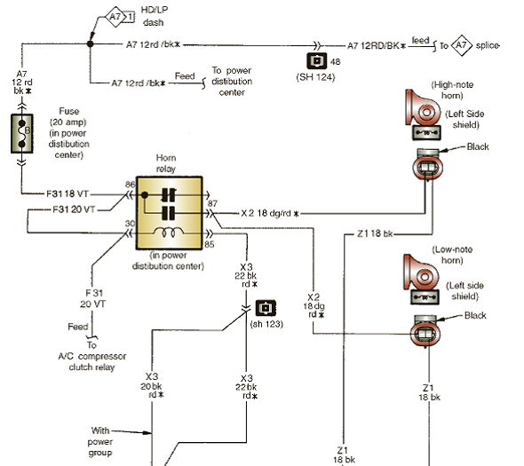
Horn Circuit Diagram Wiring Diagram
Reverse Car Parking Circuit Diagram
Car Reverse Horn Supreem Circuits Diagram And Projects
