Simple Servo Motor Diagram

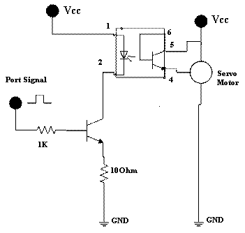
Servo Motor Driver Circuit

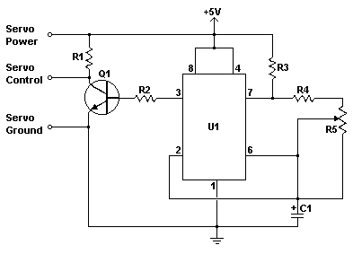
Servo Motor Controller Circuit

How To Make A Simple Servo Motor Tester Circuit Circuit
Receiver or a servo motor.
Simple servo motor diagram. The works is simple the lamp give light to the ldr light depending. It is just made up of simple motor which run through servo mechanism. Circuit diagram construction working every servo. The following is the schematic diagram of simple servo motor controller circuit.
Here sub micro size servo motor is taken as a target device and we developed servo motor driver circuit for that motor. Electronic schematic diagram for 100 watt inverter 12v dc to 220v ac. R1 820 ohm 14w. Simple servo motor controller parts list.
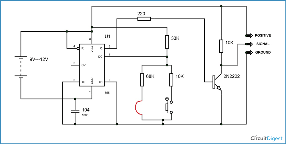
In situations like these a simple servo motor tester circuit will be helpful. Power ground and signal. A servo motor is an electrical device which can push or rotate an object with great precision. In this diagram the left screw goes to the motors signal wire white or yellow the center screw goes to its ground wire black and the right screw goes.
This is the simple basic design of servo motor controller with pulse generator. The circuit can be suitably modified to get pulses of sufficient length. The ground wire is typically black or brown and should be connected to a ground pin on the board. To do this we display ads from only trusted partners.
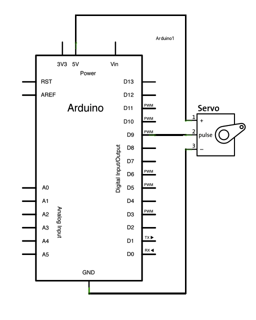
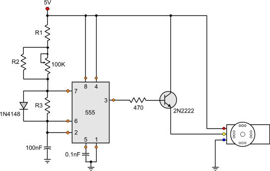
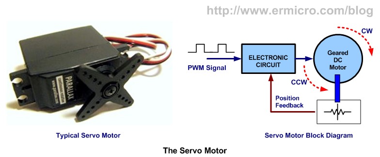
A servo is a small device that has an output shaft. Simple servo tester schematic circuit diagram. Servo motors have three wires. The power wire is typically red and should be connected to the 5v pin on the arduino or genuino board.
Simple servo tester schematic circuit diagram. This is the simple basic design of servo motor controller with pulse generator. The terminal block with three screws connects to the servo motor. It uses the cmos ic 7555 in the astable mode to generate pulses to drive the servo motor.
Control a servo motor without programming. It uses the cmos ic 7555 in the astable mode to generate pulses to drive the servo motor. Learn how to control a servo motor with a dial and a simple circuit. If you want to rotate and object at some specific angles or distance then you use servo motor.
We deliver up to date correct authentic data based on evaluation unbiased at no cost to you. Here the simple file alarm circuit based timer id ne555. You can also use this circuit to test a newly bought servo motor to check if it is a faulty one. A servo motor tester is a simple circuit designed specifically for testing the functionality of a servo motor.

Servo Driver Circuit Schematic In 2019 Simple Circuit
Servo Motor Types And Working Principle
Servo Motors Working Principle Controlling And Applications
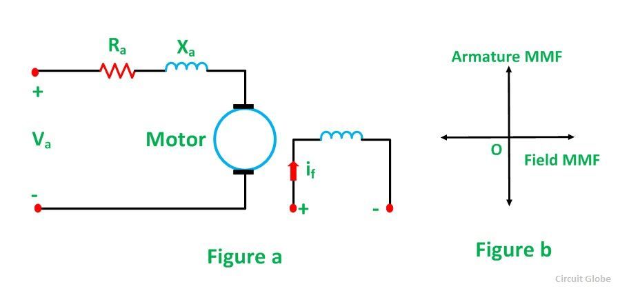
What Is A Servo Motor Ac Dc Servo Motor Circuit Globe
Simple Servo Controller
Arduino Sweep
Servo Motor Types And Working Principle
How Rc Servos Works

How Does A Servo Motor Work Quora
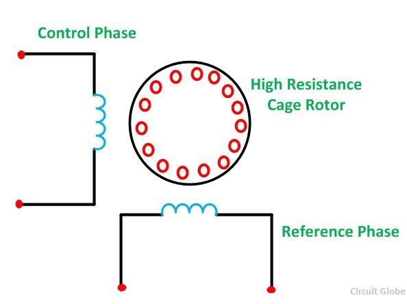
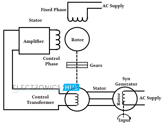
Two Phase Ac Servo Motor 3 Phase Ac Servo Motor Circuit
Servo Motor Circuit Automation Circuits Next Gr
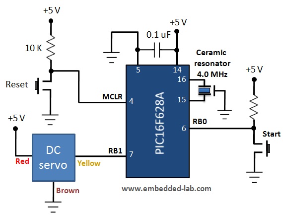
Lab 21 Servo Motor Control Embedded Lab

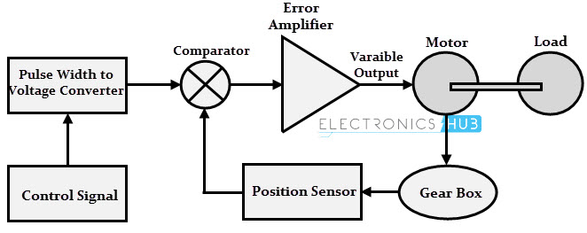
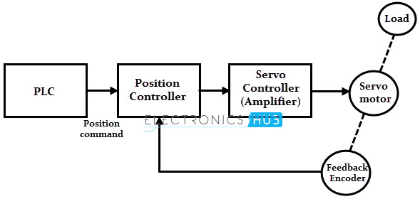
Block Diagram Of Servo Motor And Head Download Scientific

Servo Motor Controller Using 555 Ic Circuit Diagram
Servo Motor Types And Working Principle
Basic Servo Motor Controlling With Microchip Pic
Servo Motor Tester Circuit Diagram Using Ic 555

Servo Motor Control Using 555 Timer Ic Tutorial 67
